


www.ti.com
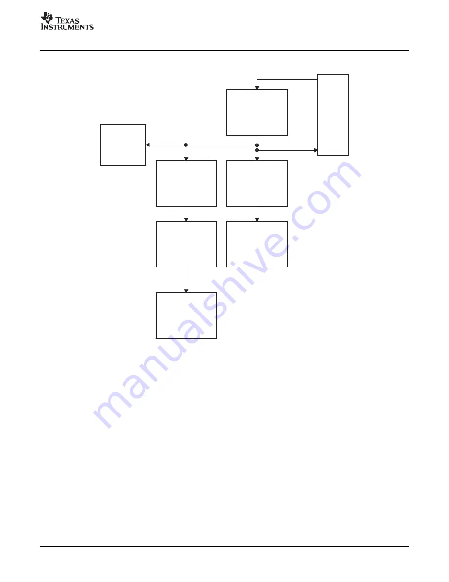
EPWM1SYNCO
ePWM1
EPWM1SYNCI
GPIO
MUX
SYNCI
eCAP1
EPWM2SYNCI
ePWM2
EPWM2SYNCO
EPWM3SYNCO
ePWM3
EPWM3SYNCI
EPWM2SYNCI
ePWM4
EPWM2SYNCO
EPWM3SYNCO
ePWM5
EPWM3SYNCI
ePWM6
EPWMxSYNCI
EPWMxSYNCO
Time-Base (TB) Submodule
Figure 2-6. Time-Base Counter Synchronization Scheme 3
Each ePWM module can be configured to use or ignore the synchronization input. If the TBCTL[PHSEN]
bit is set, then the time-base counter (TBCTR) of the ePWM module will be automatically loaded with the
phase register (TBPHS) contents when one of the following conditions occur:
•
EPWMxSYNCI: Synchronization Input Pulse:
The value of the phase register is loaded into the counter register when an input synchronization pulse
is detected (TBPHS
→
TBCNT). This operation occurs on the next valid time-base clock (TBCLK)
edge.
•
Software Forced Synchronization Pulse:
Writing a 1 to the TBCTL[SWFSYNC] control bit invokes a software forced synchronization. This pulse
is ORed with the synchronization input signal, and therefore has the same effect as a pulse on
EPWMxSYNCI.
This feature enables the ePWM module to be automatically synchronized to the time base of another
ePWM module. Lead or lag phase control can be added to the waveforms generated by different ePWM
modules to synchronize them. In up-down-count mode, the TBCTL[PSHDIR] bit configures the direction of
the time-base counter immediately after a synchronization event. The new direction is independent of the
direction prior to the synchronization event. The TBPHS bit is ignored in count-up or count-down modes.
See
Figure 2-7
through
Figure 2-10
for examples.
Clearing the TBCTL[PHSEN] bit configures the ePWM to ignore the synchronization input pulse. The
synchronization pulse can still be allowed to flow-through to the EPWMxSYNCO and be used to
synchronize other ePWM modules. In this way, you can set up a master time-base (for example, ePWM1)
and downstream modules (ePWM2 - ePWMx) may elect to run in synchronization with the master. See
the Application to Power Topologies
Chapter 3
for more details on synchronization strategies.
SPRU791D – November 2004 – Revised October 2007
ePWM Submodules
29
Submit Documentation Feedback
Summary of Contents for 28xxx
Page 2: ...2 SPRU791D November 2004 Revised October 2007 Submit Documentation Feedback...
Page 8: ...List of Tables 8 SPRU791D November 2004 Revised October 2007 Submit Documentation Feedback...
Page 12: ...Read This First 12 SPRU791D November 2004 Revised October 2007 Submit Documentation Feedback...
Page 68: ...ePWM Submodules 68 SPRU791D November 2004 Revised October 2007 Submit Documentation Feedback...
Page 116: ...Registers 116 SPRU791D November 2004 Revised October 2007 Submit Documentation Feedback...


