background image

Helpline No. UK/Northern Ireland 01422 263270   Rep. Ireland 1890 812049

Helpline No. UK/Northern Ireland 01422 263270   Rep. Ireland 1890 812049

Helpline No. UK/Northern Ireland 01422 263270   Rep. Ireland 1890 812049

3

55

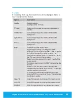
5 Edit 

L

This option is not available in the favourite list or a channel 

group. 

After entering the password (factory setting 0000), new selection 

options will appear. 

Sub-menu 

Description 

Edit

1

 Delete,

2

 Skip,

3

 Lock,

4

 Edit,

5

 Create,

6

 Del all,

Ÿź

Select, 

V- V+

 Group,   

P+P-

Page,

EXIT

 Exit. 

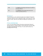
1

 Delete 

By marking with the 1 key, selected channels can be marked to be 

deleted. Please confirm selection and safety message by pressing 

the "OK“ key.  

2

 Skip 

By marking with the 2 key, selected channels can be marked to be 

skipped. Please confirm selection and safety message by pressing 

the "OK“ key. Then, the selected channels are skipped when 

zapping. A direct input is still possible. 

3

 Lock 

By marking with the 3 key, selected channels can be marked to be 

locked. Please confirm selection and safety message by pressing the 

"OK“ key. Then, the selected channels require the entry of a 

password (parental lock). 

Summary of Contents for DIGITAL MINI SATELLITE SYSTEM

Page 1: ...S SUPPORT UK N IRELAND HELPLINE NO 01422 263270 REP IRELAND HELPLINE NO 1890 812 049 Now you have purchased a Tevion product you can rest assured in the knowledge that as well as your 3 year parts and...

Page 2: ...Helpline No UK Northern Ireland 01422 263270 Rep Ireland 1890 812049 Overview of equipment Front side of the receiver Rear side of the receiver Remote control...

Page 3: ...4 CH key Switches to the next higher channel location Cursor moves up 5 CH key Switches to the next lower channel location Cursor moves down 6 Standby Switches on and switches to the standby mode Rear...

Page 4: ...s to previously selected channel 13 PAUSE Stills the frame 14 INFO Displays reception data of the current channel satellite finder function 15 0 9 Selects channel directly numerical input 16 P In norm...

Page 5: ...called the receiver in short and x the antenna unit with installation material We assume that users of the satellite system have overall knowledge regarding handling audio and video equipment Every p...

Page 6: ...scription 14 Quick guide 17 Antenna installation 18 Installation of the antenna 18 Installation options 21 Receiver connection 30 LNB cable installation 31 Connection with the Scart cable 33 Connectio...

Page 7: ...te antenna 57 System Setup symbol gearwheel 61 Tools symbol tools 65 Software update via satellite 66 Keys with special functions 67 Switch between TV and SAT 67 Switch between TV and radio 67 ZOOM 67...

Page 8: ...V cable a 11 V max 14 V DC supply as per specifications x Ensure that the total power consumption by the antenna connection of the receiver does not exceed LNB IN 300 mA x Disconnect the external pow...

Page 9: ...film Correct position x Place the receiver on a stable and even base x Use the receiver only in adequate climatic conditions x Avoid proximity to heat sources like e g heaters naked flames like e g c...

Page 10: ...cceptable manner according to the prevailing statutory regulations Never throw the batteries into normal household waste x Never expose the batteries to open fire or strong heat as otherwise there is...

Page 11: ...ideal for mobile use camping or caravans As there are diverse installation options the system can be used in many places x on at tables x at masts x at walls x on lawns x on crates x etc L Please obse...

Page 12: ...cult access Mount the satellite system only in places where it will be easily accessible to you without any danger Make sure that in case of need you will always be able to remove the system Any other...

Page 13: ...recommend packing these pieces again in the box when dismounting the system No Pieces Description without figure 1 Operating manual 1 1 Transport bag 2 1 Antenna with base 3 1 Digital satellite receiv...

Page 14: ...ready been preset The following satellites have been preset by the factory x Astra 19 2E x Hotbird 13 0E x T rksat 42 0E x Sirius2 5 0E x Amos Atlantic4 5W x Astra 28 2E x HispaSat 30W x Eutel W3A 7E...

Page 15: ...x Hungarian x Danish x French x Swedish x Croatian Further features x Software update via satellite ASTRA 19 East or via the RS232 connection on the rear side of the device x Short switching time fast...

Page 16: ...ceiver x Super fast videotext with a memory of 800 pages x Digital radio reception background image for radio background display x Additional channel information is displayed when the channel is chang...

Page 17: ...eceiver to the equipment Install the LNB cable Connect the LNB cable to the antenna Direct the antenna roughly Insert the batteries in the remote control Connect the receiver and the equipment to the...

Page 18: ...p 1 Place the antenna with its base on a suitable surface and open it in the direction of the arrow until it is in a vertical position Step 2 Now the antenna is open For fixing the angle of inclinatio...

Page 19: ...2 screws of the LNB bracket and remove the top half of the LNB bracket Then insert the LNB as shown in the picture and fix the top cover again with the screws and nuts Tighten the screws uniformly L P...

Page 20: ...LNB bracket is locked While you are doing this press the clip with the button for installation slightly down Step 5 Now the antenna is completely installed Fix the antenna cable at the LNB The instal...

Page 21: ...tellite system the cable must be fixed at the LNB L Please observe all prohibitions or information of the local administration if any L When selecting an installation place you should make sure in any...

Page 22: ...section Direction of the antenna on page 37 Caution You can protect the sensitive surface from scratches and pressure marks by placing a piece of felt cardboard or similar on it L Put sufficient weigh...

Page 23: ...base to get the required stability The cavities of the lateral rods must face towards the inside of the base Now the lateral rods rest directly on the base The spring ring and the plain washer must be...

Page 24: ...e system the antenna can be directed to the desired satellite For this please proceed as described in the section Direction of the antenna on page 37 L For achieving a safe installation on the mast pl...

Page 25: ...e cavities of the lateral rods must face towards the inside of the base Now the lateral rods rest directly on the base The spring ring and the plain washer must be placed between the lateral rods and...

Page 26: ...t with the four screws After the cabling of the satellite system the antenna can be directed to the desired satellite For this please proceed as described in the section Direction of the antenna on pa...

Page 27: ...installed antenna on the lawn You can fix the base of the antenna e g with tent pegs see arrows on the lawn to protect it against external influences such as wind displacement or tipping over After t...

Page 28: ...The spring ring and the plain washer must be placed between the lateral rods and the wing nuts Here the plain washer rests on the respective lateral rod The spring ring must be placed between the pla...

Page 29: ...UK Northern Ireland 01422 263270 Rep Ireland 1890 812049 29 31 L To achieve a higher stability the bottles in the crate should be filled For achieving a safe installation please make sure that the pla...

Page 30: ...all equipment and the antenna properly Otherwise the receiver can suffer damages The wire netting and the inner core of the coaxial cable carry current during operation L Usage for camping or in cara...

Page 31: ...ut 10 mm of the outer insulation so that the wire netting is exposed Turn the wire netting backwards and wind it over the outer insulation in such a manner that it does not touch the inner core Remove...

Page 32: ...n Ireland 01422 263270 Rep Ireland 1890 812049 32 34 Installation diagram Fasten the F connector of the coaxial cable onto the LNB IN antenna connection of the receiver Fasten the other end of the coa...

Page 33: ...art cable in the Scart socket TV on the receiver Connect the Scart cable to the TV set Follow the operating manual of the TV set Insert the Scart cable in the Scart socket VCR of the receiver if you w...

Page 34: ...Helpline No UK Northern Ireland 01422 263270 Rep Ireland 1890 812049 34 36 Connection diagram...

Page 35: ...ver it may damage your stereo system Strictly follow the instructions for connecting the Cinch cable given in the operating manual of your stereo system L The Cinch cable is not included in the produc...

Page 36: ...1890 812049 36 38 Connection of the coaxial digital output Insert the coaxial cable in the COAXIAL socket or the receiver Connect the coaxial cable to the audio digital receiver Connection diagram L...

Page 37: ...ntenna is determined by two angles x the horizontal azimuth angle haa x the vertical elevation angle vea L When searching the southern direction the position of the sun might help you During summer ti...

Page 38: ...uch the house wall L Please make sure that there are no obstacles between the antenna and the satellite No tree house or other obstacles must block visibility As a general rule an obstacle may only be...

Page 39: ...ite from which you would like to receive signals While doing this set the horizontal azimuth angle When you have directed the antenna towards your desired satellite you must set the elevation angle ve...

Page 40: ...Helpline No UK Northern Ireland 01422 263270 Rep Ireland 1890 812049 40 42 Tighten the wing nuts as soon as the desired elevation is attained...

Page 41: ...31 00 32 00 Dublin 25 00 26 60 28 00 29 00 21 50 25 00 Hamburg 28 00 28 80 22 00 29 00 26 60 19 00 Kopenhagen 26 30 26 60 26 00 25 00 London 28 40 25 40 31 00 31 00 25 40 24 80 Madrid 37 70 40 00 42...

Page 42: ...simultaneously and use batteries of the same type Check the batteries of your remote control at least once a year If one of the batteries has leaked wear protective gloves and clean the battery compar...

Page 43: ...green LED is off If you wish to operate the receiver with 12V insert the 12V mains cable in the DC IN socket and connect it to your power source Caution In case of vehicles with an on board power supp...

Page 44: ...additionally to support you during the fine tuning process A stronger and higher signal indicates a better direction of the antenna As soon as the signal quality has reached approx 60 the channel imag...

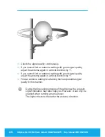
Page 45: ...n with good reception quality you must tighten the wing nuts again to fix the antenna Slowly turn the antenna horizontally towards the right and subsequently towards the left L A digital satellite rec...

Page 46: ...tion by 1 If you cannot find an antenna setting with good signal quality adjust the antenna again in vertical direction by 1 Find an antenna setting for attaining the best possible signal quality in t...

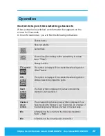
Page 47: ...Time Storage location TTX symbol This symbol is displayed if the selected broadcasting station offers Teletext EPG symbol This symbol is displayed if the selected broadcasting station offers an electr...

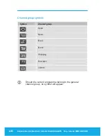
Page 48: ...and 01422 263270 Rep Ireland 1890 812049 48 50 Channel group symbols Symbol Channel group Sport News Music Movie Shopping Education Leisure L Should the current programme belong to the general channel...

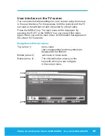
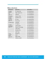
Page 49: ...need to be switched on and connected by a Scart cable Press the MENU key The main menu will be displayed By pressing the EXIT or the MENU key you can exit this menu again When you exit the main menu a...

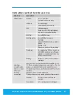
Page 50: ...TP Scan See following text Installation symbol Satellite antenna page 5 Preset Scan See following text Language See following text TV System See following text Channel setup See following text Time T...

Page 51: ...the menu again Changes must be confirmed with the OK key Apart from this the numerical keys are required in further sub menus L In each menu an information bar will be indicated containing all selecti...

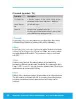
Page 52: ...nnels a heart symbol will be displayed 2 Move By pressing 2 key the move symbol will appear behind the marked channel By pressing the keys CH and CH the channel will be moved to the desired position T...

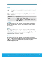
Page 53: ...EXIT Exit 1 Delete By marking with the 1 key selected channels can be marked to be deleted Please confirm selection and safety message by pressing the OK key 2 Skip By marking with the 2 key selected...

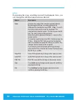
Page 54: ...with the keys 1 2 and 3 of the remote control For deleting a symbol mark the DEL field and press the OK key Select the OK field as soon as the channel name is complete and press the OK key to confirm...

Page 55: ...channel name By pressing the OK key an editing mask will be displayed By pressing the keys CH CH V and V the curser can be moved over the keyboard The selected field is marked yellow To select it pres...

Page 56: ...ey 6 Del ete all Via the 6 key you can mark all channels to be deleted Thereafter individual channels can be deselected again by pressing the 1 key Please confirm selection and safety message by press...

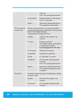
Page 57: ...Disable for positioner Not enabled Positioner By pressing the OK key you will go to DiSEqC positioner menu Please refer to the operating manual of your DiSEqC motor for help Antenna setup Polarity Hor...

Page 58: ...ction of the satellite to be scanned TP Index Frequency selection The selection options are displayed 1 Add 2 Delete 3 Del all See following table for TP Index TP Frequency Setting of the frequency Sy...

Page 59: ...70 Rep Ireland 1890 812049 Helpline No UK Northern Ireland 01422 263270 Rep Ireland 1890 812049 59 61 Free only unencrypted channels Scan Channel Selection between TV and radio or only TV or only radi...

Page 60: ...onder is created after execution When exiting the menu confirm the safety message by pressing the OK key Only after confirmation the new frequency will be created For scanning the newly created freque...

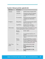
Page 61: ...n system Default selection Auto TV System Aspect Mode Selection of the aspect ratio Default selection 4 3 Letterbox Startup channel Determination of the desired TV or radio channel appearing when swit...

Page 62: ...ad Default OSD Setting The default OSD setting can be restored The default password is 0000 Menu Lock Disabling of password input in the Installation menu Channel Lock Disabling of password input for...

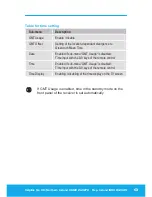
Page 63: ...of the location dependant divergence to Greenwich Mean Time Date Enabled if sub menu GMT Usage is disabled Time input with the 0 9 keys of the remote control Time Enabled if sub menu GMT Usage is disa...

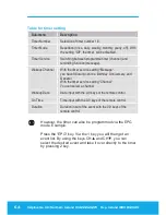
Page 64: ...ce setting Message you have following options Birthday Anniversary and General With the timer service setting Channel You can select a channel Wakeup Date Date input with the 0 9 keys of the remote co...

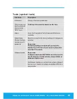
Page 65: ...and Othello are available Default Value Factory Settings requires input of password Reset the receiver to the factory settings All changes are cancelled Please note The factory settings are restored...

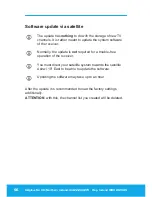
Page 66: ...m software of the receiver L Normally the update is not required for a trouble free operation of the receiver L You must direct your satellite system towards the satellite Astra1 19 East to be able to...

Page 67: ...e TV Radio key you can switch between TV and the radio function Now the receiver transmits a radio channel and shows a background image To return to the TV channel press the TV Radio key of the remote...

Page 68: ...lowing event will be displayed For getting detailed information on the current event press the 2 key Press the 1 key to display the complete event list of the selected channel With the keys V and V yo...

Page 69: ...your screen starting with the current channel With the keys CH CH V and V you can move the yellow marking bar The marked channel is displayed in real time All other channels are displayed as freeze im...

Page 70: ...urrent reception parameters you will get information on the signal strength and quality Additionally you can enable an acoustic signal by pressing the 1 key L An acoustic signal will be emitted by the...

Page 71: ...Dismantle the antenna unit Pack the receiver the remote control the 2 batteries the external power pack and the 12V cable for the cigarette lighter into the corresponding cardboard box and put it into...

Page 72: ...agent containing solvents like petrol or thinners for cleaning These agents may damage the surface of the casing Clean the casing of the receiver with a dry cloth Clean the antenna and mounting compo...

Page 73: ...t a current channel from the preset channel list and then press the INFO key Front Panel LEDs dark The external power pack and or the 12V cable are not connected Connect the external power pack and or...

Page 74: ...t come to the improbable case of a system crash separate the receiver from the mains supply Connect it again after 10 seconds With this the problem can usually be solved Please note a system crash is...

Page 75: ...e contact the service hotline if you have forgotten your personal password Default value The factory settings are restored if you keep the standby key at the face of your receiver pressed for more tha...

Page 76: ...proper manner Never throw the batteries into normal household waste Batteries may contain toxic agents Therefore it is essential to dispose of the batteries according to the prevailing statutory regu...

Page 77: ...13V 18V GS 0 30 A max overload protection LNB control 22 kHz 2 kHz 0 6 V pp 0 2 V DiSEqC control Version 1 0 Version 1 2 tone burst A B Symbol rate 1 35 MS s Input speed Max 15 Mbit s Error correction...

Page 78: ...utput voltage 12 V 1 0 A Weight power pack in grammes 108 g Receiver input voltage 11 14 V Power consumption receiver approx 12 W operation with Single LNB approx 4 W standby Operating temperature 0 C...

Page 79: ...9 82 Declaration of conformity The manufacturer hereby declares conformity with the following guidelines and standards for this product Low voltage guideline 73 23 EEC x EN 60 065 Guideline on electro...

Page 80: ...es Free of charge services that can be received without special decoder LNB LNC Low Noise Block Amplifier Converter A device at the centre of the antenna which converts high frequency incoming signals...

Page 81: ...and 1890 812049 Helpline No UK Northern Ireland 01422 263270 Rep Ireland 1890 812049 81 84 VCR Abbreviation for Video Cassette Recorder This product must be disposed of correctly Please contact your L...

Page 82: ...e problematic as a general rule of thumb look to place the dish as high as possible the provided cable will allow a reasonable height to be achieved A small difference in the location of the dish can...

Page 83: ...1 Identify due south with a compass 2 Place the enclosed SATELLITE MAP on the ground in line with your dish and with the SOUTH arrow aligned correctly with the aid of the compass 3 Set the elevation o...

Page 84: ...lite This typically takes place with no more than a 10 to 15 mm movement in the LNB arm quite a fine adjustment it is easy to see now why just moving the dish about and hoping will not work 4 Move the...

Page 85: ...049 85 so for the south of England elevation is about 5 degrees and for the north of Scotland the elevation needs to be minus i e the dish needs to be leaning forward 2 3 degrees NOTE You can also use...

Page 86: ......

Page 87: ...s proof of date of purchase The guarantee can only be extended for the duration of any repair required During the warranty period defective devices can be sent freight prepaid to the service address s...

Page 88: ...890 812 049 KEY ELECTRONICS UNIT 20 ENTERPRISE CITY MEADOWFIELD AVENUE SPENNYMORE COUNTY DURHAM DL16 6JF In order to deal with your enquiry as quickly and efficiently as possible please contact the be...

Reviews: