Teuco 2WSC18 Assembly Instructions Manual Download Page 15

15

OPENING THE PACKING

Remove the crate and packing, leaving the minipool on the pallet.

Whatever transport and handling operations are involved, use only

the pallet on which the minipool is packed for shipment.

REMOVING THE COVER

Remove the cover (art. 627 only: unhook the retaining straps at the four
corners).

The cover is not intended to carry weights.
Do not sit, step or lie on the cover.
Do not place objects on the cover.
The canvas can be dangerous if not secured or properly closed.
Failure to follow the instructions for securing the canvas can result
in danger to the user.
Remove the canvas completely before stepping into the pool,
otherwise there is a risk of being trapped.

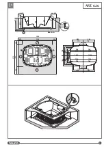
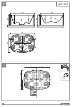
REMOVING THE PROFILES

Remove the protective profiles located between the panelling and the
edge of the minipool.

REMOVING WOOD PANELS

Unscrew the screws (A) at the base of the panels and pull the panels
towards you (B) so that they come away from their seating.
Lift the panel until the top sections are released (C) then remove each
panel from the structure securing it in place in numerical order.

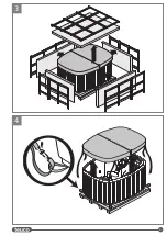
FITTING THE LIFTING BARS

Insert the lifting bars into the sides of the frame and secure them with
the special screws and nuts.

NEVER LIFT THE MINIPOOL BY THE RIM OR BY THE PIPELINES.
THE MINIPOOL MUST NEVER BE LIFTED WHEN FULL OF WATER.
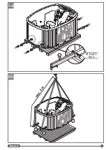
PLACEMENT

When lifting and placing the minipool, use slings of suitable load
capacity at least 4 metres in length (distance from the bars on the
minipool frame to the lift hook).

Slip the slings over the bars (B) and proceed to lift the minipool, then
place it on the selected site (the weight of the minipool when empty is
approximately 350 kg).
Remove the bars (B) and keep handy for future use, if needed.

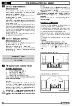
PLUMBING CONNECTIONS

DRAIN CONNECTION

The Teuco minipool has a gate type drain valve with a 
ø 40 mm connection.
Connect the valve to the main drain by way of a trap (see preinstallation
data sheet - step 2).

FILL CONNECTION

The recommended method of filling the Teuco minipool is to use a hose
(taking care not to immerse the end as this could cause a reflux of water
back into the main).

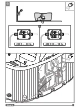
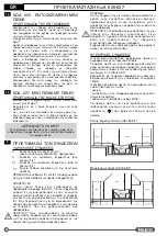
HEAT EXCHANGER CONNECTIONS

The minipool is provided with a switch box (

M

) containing a relay with a

"normally open voltage-free" contact  (3A Max - spare terminals
connected to Black and White conductors)  that can be used as an
on/off switch control for a boiler,  a recirculation pump, a zone valve or
other appliance/component. The electrical connection to the box must
be permanent, able to handle the rated current, and specified to liquids
ingress protection category IPX5. Install the pipes  (

C

and

C1

) carrying

water to and from the boiler as indicated.

ELECTRICAL CONNECTIONS

Make the connection to the A.C. power supply at the terminal box (D)
provided on the minipool.
Electrical connections must be made in compliance with safety
regulations, as indicated in the preinstallation data sheet (step 2).
The size of the power cable and the relative clamp must be selected
according to the current load, the distance from the junction box and the
way the cable is laid and routed.
The jobs of drilling the terminal box and selecting and fitting the IPX5
clamp are the responsibility of the installer.

Having made all the connections, check that the system operates
correctly (see user manual - STARTING UP FIRST TIME).
CAUTION: POWER UP THE ELECTRICAL EQUIPMENT ONLY
AFTER THE MINIPOOL HAS BEEN FILLED WITH WATER.

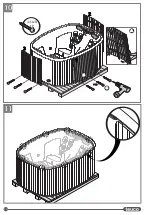
FITTING WOOD PANELS (Art. 627)

Hook the top part of the panel into the special hooks on the frame (A).
Place the panels below the rim of the minipool (B).
Fix the panels to the minipool using the special screws supplied (C).
Fit the panels in numerical order.

FITTING THE PROFILES

Insert the protective profiles between the panelling and the edge of the minipool.

11

10

9

HEAT EXCHANGER SPECIFICATIONS

Minimum output of boiler  

. . . . . . . . . . . . . . . . . . . . . . . . . . . . . . . . . . . . . . . . . .

7 Kw

Maximum flow of recirculation pump (P)

. . . . . . . . . . . . . . . . . . .

1600 l/h

Minimum head of recirculation pump (P)

. . . . . . . . . . . . . . . .

1.8 m.c.a.

Max water temperature in boiler

. . . . . . . . . . . . . . . . . . . . . . . . . . . . . . . . . . .

80°C

Boiler pipe connections

. . . . . . . . . . . . . . . . . . . . . . . . . . . . . . . . . . . . . . . . . . . . . . .

3/4"

8

7

6

B

6

A

5b

5a

4

3

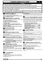
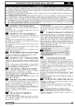
INSTRUCTIONS FOR INSTALLATION Art. 626-627

GB

The product must be installed exactly as supplied by Teuco, otherwise the warranty will be invalidated.

The directions for installation must be observed to the letter, as must those concerning recommended materials and the accessories
supplied with the product.

Electrical connections must be carried out in compliance with national safety regulations, as indicated in the preinstallation data sheet.

This manual constitutes an integral part of the product and must be kept for future reference.

Data and specifications indicated are not binding to the company: Teuco Guzzini SpA reserves the right to make such changes as are

deemed appropriate without prior notice and without any obligation to update.

This product is intended for home use. In the event of a Teuco minipool being commissioned for public use, procurement managers

must ensure compliance with all statutory regulations governing safety, water treatment and utility systems normally in force in the
country of installation.

WARNINGS


Summary of Contents for 2WSC18

Page 1: ...S INSTRUCTIONS POUR LE MONTAGE MONTAGE ANWEISUNGEN INSTRUCCIONES DE MONTAJE MONTAGE INSTRUCTIES INSTRU ES PARA A MONTAGEM HCTPYK O MOHTA Y INSTRUKCJE MONTA U MONTAJ TALIMATLARI UPUTSTVA ZA MONTA U HR...

Page 2: ...Nettogewicht Peso neto Netto gewicht Peso l quido fi Ci ar netto Net a rl k Neto te ina 242 kg ART 626 Carico sul pavimento Floor load Charge au sol Bodenbelast Carga al pavimiento Belasting op de vl...

Page 3: ...A B A A A 788 688 695 A A min 400 min 400 884 773 261 261 773 884 261 261 773 773 884 884 968 1016 1063 1016 968 968 968 1016 1063 1016 788 788 688 688 633 633 542 542 428 428 700 400 400 400 1640 A A...

Page 4: ...4 230 300 380 645 175 820 820 430 1082 5 1082 5 O C1 C 1640 A A B B 2165 A A 2165 915 65 980 A A 2165 915 65 980 788 688 695 500 638 590 1445 1340 1B 2 ART 627...

Page 5: ...5 3 4...

Page 6: ...6 5a 4 5x25 x9 A A B B 1 1 2 2 3 3 C C 5b...

Page 7: ...7 m i n 4 m 6b 6a M10x40 M10...

Page 8: ...8 40mm CALDAIA 3 4 3 4 7 8...

Page 9: ...9 9...

Page 10: ...10 4 5x25 x9 1 1 2 2 3 3 A A B B C C 10 11...

Page 11: ...e 626 627 16 Montage Anweisungen 626 627 18 Instrucciones de Montaje 626 627 20 Montage Instructies 626 627 22 IInstru es para a Montagem 626 627 24 626 627 26 626 627 28 Instrukcje monta u 626 627 30...

Page 12: ...tacco 40 mm Per lo scarico si pu utilizzare un tubo flessibile da collegare alla valvola oppure si pu effettuare un collegamento fisso con la tubazione di scarico O In questo caso per agevolare lo sca...

Page 13: ...ne e lo spegnimento di una caldaia di una pompa di ricircolo di una valvola di zona o altro Predisporre inoltre i tubi idraulici C e C1 tra caldaia e scambiatore rispettando il verso di percorrenza de...

Page 14: ...valve with 40 mm connection The tub can be emptied simply by connecting a hose to the valve or alternatively by making a permanent connection to the main drain O In this instance it will be advisable...

Page 15: ...e electrical connection to the box must be permanent able to handle the rated current and specified to liquids ingress protection category IPX5 Install the pipes C and C1 carrying water to and from th...

Page 16: ...mm Pour l vacuation relier un tuyau flexible la valve ou r aliser un raccordement fixe avec le conduit de vidange O Dans ce cas il est conseill de pr voir un puisard muni d une valve utiliser comme va...

Page 17: ...arr t d une chaudi re d une pompe de recyclage d une vanne de zone ou autre Le raccordement lectrique au bo tier doit tre de type fixe appropri la consommation avec degr de r sistance la p n tration d...

Page 18: ...inem Bodenventil mit Anschluss 40 mm ausgestattet F r den Wasserablauf kann man einen Schlauch verwenden der an das Ventil angeschlossen wird oder einen festen Anschluss mit der Ablaufleitung O ausf h...

Page 19: ...che Anschluss an den Schaltkasten muss ortsfest unter Ber cksichtigung der Stromaufnahme und mit Schutzart IPX5 gegen das Eindringen von Fl ssigkeiten ausgef hrt werden Bereiten Sie weiterhin die Wass...

Page 20: ...n previsto nicamente cuando la minipiscina viene equipada con cambiador de calor DESAG E La minipiscina Teuco cuenta con una v lvula de fondo con empalme de 40 mm Para el desag e se puede conectar a e...

Page 21: ...riente absorbida y herm tica a la penetraci n de l quidos IPX5 Predisponer adem s los tubos hidr ulicos C y C1 entre la caldera y el intercambiador respetando el sentido de circulaci n del agua CONEXI...

Page 22: ...r kan een flexibele leiding gebruikt worden die op de klep wordt aangesloten of kan met behulp van een afvoerbuis O een vaste verbinding gecre erd worden In dit geval wordt voor een goede waterafvoer...

Page 23: ...chikt voor de opgenomen stroom en met een weerstandsgraad tegen het binnendringen van vloeistoffen van IPX5 Maak bovendien de hydraulische aansluitingen C en C1 tussen de verwarmingsketel en de warmte...

Page 24: ...de fundo com liga o de 40 mm Para a descarga pode utilizar se um tubo flex vel a ligar v lvula ou efectuar se uma liga o fixa com a tubagem de escoamento O Neste caso para acelerar a descarga aconsel...

Page 25: ...ona ou outra A liga o el ctrica caixa deve ser de tipo fixo adequado corrente absorvida com grau de resist ncia penetra o de l quidos IPX5 Prepare tamb m os tubos hidr ulicos C e C1 entre a caldeira e...

Page 26: ...oe e o o 40 o e A 70 o e 0 3 2 S 627 643 2 O 40 C 3 4 C1 3 4 1 Teuco 40 Teuco CEI 64 8 3 0 1 2 CEI 64 8 7 30 IPX5 CEI 64 8 7 CEI 64 8 7 2 5 m 2 m 1 5 m 2 m 1 5 m ZONA 2 ZONA 2 ZONA 1 ZONA 0 ZONA 0 2 5...

Page 27: ...e e a a o a e e e e o e o o o e o a a o o a e e e e o o a a e o o o e e e e o a o a e a a e e A B C 4 350 Teuco 40 2 3 IPX5 1 D 2 IPX5 Art 627 A B C 11 10 9 7 Kw 1600 1 8 80 C 3 4 8 7 6B 6A 5b 5a 4 3...

Page 28: ...i 3 4 C1 fi fi 3 4 fi C C1 fi fi Teuco fi 40 mm fi Teuco fi fi fi fi fi fi fi CEI 64 8 fi fi fi 3mm fi 0 1 2 CEI 64 8 7 fi fi fi fi 30mA fi 5 fi fi fi fi CEI 64 8 7 CEI 64 8 7 2 5 m 2 m 1 5 m 2 m 1 5...

Page 29: ...euco 40 mm 2 fi fi fi fi M 3A Max fi fi fi IPX5 C C1 D fi 2 fi fi IPX5 fi fi 627 fi C fi 11 10 9 9 7 Kw P 1600 l h fi P 1 8 80 C 3 4 8 9 7 6B 6A 5b 5a 4 3 626 627 GR fi fi fi Teuco fi fi fi fi fi fi f...

Page 30: ...u rurowego pod czanego do zaworu albo mo na wykona sta e przy cze za pomoc rury wylotowej O W tym przypadku w celu u atwienia spuszczania wody zalecamy przygotowanie studzienki z zaworem s u cej jako...

Page 31: ...w strefie lub innego urz dzenia Przygotowa ponadto rury hydrauliczne C i C1 pomi dzy kot em i wymiennikiem przestrzegaj c kierunku przebiegu wody PRZY CZA ELEKTRYCZNE Wykona po czenie z sieci elektry...

Page 32: ...i havuz s de ifltiricisi ile temin edildi inde gerekli olmaktad r BOfiALTMA Teuco mini havuzun alt na 40 mm ap nda bir boflaltma valf tak lm flt r Boflaltma i in valfa tak lan esnek bir boru kullan l...

Page 33: ...z ve Siyah iletkenlere ba l bofl kablolar bir kontak olan bir elektrik kutusu M donan m mevcuttur Ayr ca kazan ve de ifltirici aras ndaki borular C e C1 suyun ak fl y n ne g re haz rlay n ELEKTR KSEL...

Page 34: ...ra 40 mm Na ventil mo ete priklju iti crijevo ili pak odlu iti se za vrsti priklju ak pomo u odvodnih cijevi 0 U ovom slu aju olak ati ete odvod ako ugradite jamicu s ventilom koja e se koristiti kao...

Page 35: ...ne zone i druge svrhe Elektri ni priklju ak ove kutije mora biti pri vr en primjeren elektri nom kapacitetu i imati vodootpornost i nepropustivost tipa IPX5 Unaprijed postavite osim toga vodovodne cij...

Page 36: ...Industriestra e 161c 50999 K ln Rodenkirchen Tel 02236 74780 Fax 02236 747829 Freecall 0800 100 8826 www teuco de E mail info teuco de France Teuco France Z I Les Algorithmes 141 145 Rue Michel Carr 9...

Reviews: