TET Electronics HERCULES-2500 Instruction Manual Download Page 7

3. Installation 
 

Before using the power-supply HERCULES, a power cord (5-wire) has to be plugged in the Acinput 
(TB1) of the backpanel of the power-supply. The power cord should at least support 3x15A or 3x25A 
load. The three phases, neutral and earth have to be connected. 
 

Caution: Operation without connected neutral causes a break down of the power supply unit. 
 

The HERCULES supply is immediately operational after powering up, and a soft start time of approx. 
3 sec. 
 

If the power supply will be switched off under full load, it is necesarry to have a delay of  
10sec. before switching on again. 
 

The warm-up time, at room temperature, in order to reach the high stability specifications is 
negligible. 
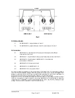
The two sliding switches S1 and S2 must be positioned on the bottom side (see chap. 7.2b, 
7.2f, 7.4b and 11a too.) 
 

Note: 

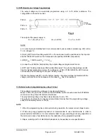
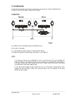
The outputs of the power source should not be connected to AC- sources, DC- sources with 

reverse polarity or DC-sources with higher voltage than 1.2 x U

nominal

 If such an operating mode is 

inevitable (e.g. charging batteries, paralleling power sources or working with heavy inductive loads), 
the customer must assure proper safety measures ( e.g. OR-ing diodes, fuses etc.). 


4. Constant voltage mode with current limiting 
 

This mode of operation is reached, when the LED-indicator 'CV' lights up. Because of the high stability 
of HERCULES it is possible, to adjust accurately the output voltage to several decades. For this, an 
adequate digital voltmeter should be used. The local adjustment is performed using the voltage control 
knob 'VOLTAGE'. 
The adjustment to the desired and limited current is achieved by short-circuiting the output and using 
the current limiting control knob while reading the display. 


5. Constant current mode with voltage limiting 
 

This mode of operation is reached when the LED indicator 'CC' lights up. The height of the constant 
current is locally adjusted using the current control knob 'CURRENT'. The lower limit for the constant 
current operation is 100mA. It is important, to be careful, particularly when working with small output 
currents, since the charging or discharging currents of the output capacitor affects the constant 
current, depending on the charging condition of the output capacitor under dynamic loading condition. 
The output voltage to be maximum limited is adjusted by using the voltage control knob and reading 
the display. 


Hercules 5000 
     Page 

von 

17 

   ISSUE 

07/05 

Summary of Contents for HERCULES-2500

Page 1: ...pine Allee 1 D 94513 Sch nberg Tel 49 0 85 54 9609 0 Fax 49 0 85 54 96 09 20 Mail sales tetelectronics de INSTRUCTION MANUAL HERCULES 5000 High performance power supplies Hercules 5000 Page 1 von 17 I...

Page 2: ...voltage operation with current limiting 5 Constant current operation with voltage limiting 6 Sensing compensation 7 External programming 8 Overvoltage protection 9 Serial mode 10 Parallel mode 11 Tra...

Page 3: ...t adjustable with a 10 turn potentiometer Regulation accuracy LINE 0 01 by 10 line fluctuation LOAD 0 1 from full load to short circuit Temperature coefficient 0 01 K measured in a range of 0 50 C 1 W...

Page 4: ...ator 7 Remote enable indicator 8 LED indicator for constant voltage mode 9 LED indicator for constant current mode 10 Adjustment control for the OV protection 11 Overvoltage reset button and overvolta...

Page 5: ...AC input and TB1 three phase 5 wire 4 Terminal block for sense line and output voltage V V TB2 5 Opt 34 IEEE bus interface connector address switches and RS 232 connector 6 Regulation board with TB3...

Page 6: ...B 4 15 U PROG Setting and Function see chapter 7 2 and 7 4 TB 3 PIN LAYOUT 15 Pin Sub D connector RVP TRACKIG TB3 TB4 ON OFF ON OFF TB 3 1 SLAVE TB 3 2 MASTER TB 3 3 RCP TB 3 4 10V REF TB 3 5 TRACKING...

Page 7: ...ustomer must assure proper safety measures e g OR ing diodes fuses etc 4 Constant voltage mode with current limiting This mode of operation is reached when the LED indicator CV lights up Because of th...

Page 8: ...al programming The output voltage current and OV protection can be adjusted externally with programming voltages The voltage and current can also be adjusted by means of resistance programming NOTE Po...

Page 9: ...g mode f When the sliding switch S1 is in the bottom position the output voltage is adjusted with the voltage control knob on the frontpanel In this case Rprog has to be removed 7 3 External current p...

Page 10: ...xImax by the primary current limiting of the inverter In this case however the CC LED on the frontpanel will not illuminate 7 5 External OV programming see chap 8 too NOTE The regulation board is deli...

Page 11: ...power switch must be ON 7 8 Automatic switchover If the bus activates the IEEE interface the power supply switches automatically in EXTERN REMOTE mode The command LOCAL switches then automatically ba...

Page 12: ...The OV RESET signal can be generated using a relay contact or a logic signal Contact will be established between TB 3 7 and TB 3 14 The logic signal is high active and should have a high level between...

Page 13: ...ut voltages are adjusted via the corresponding VOLTAGE Pots The total output voltage is the sum of the two adjusted voltages When the current limit values are not equal the higher value applies as val...

Page 14: ...ot possible to ensure a simultaneously switch off of the devices in case of an over voltage decoupling diodes should be used In that case a sensing compensation is not possible see also point 8 If an...

Page 15: ...and so on 2 9 TB 4 15 of first slave to TB 3 4 of first slaves This one do for all slaves again 3 Please note 3 1 All HERCULES power supplies have to be switched on and off simultaneously 3 2 In view...

Page 16: ...R1 should be oversized eg 2W with a Tc of 20ppm C NOTE a In tracking mode the slave HERCULES is to be set in RVP mode S1 right EXTERN not pushed However a programming resistor is not connected conseq...

Page 17: ...illuminates red Simultaneously the output power is slowly diminished During this state only the MOSFET s temperature approx 85 C is regulated The LED indicators CV and CC do not light up as ARGOS unde...

Reviews: