


8.1 Treshold adjustment:
1. OV control (described as OV adjust on frontpanel) is to be turned clockwise with a screw-
driver until it stops (highest Threshold)
2. Power-up device and adjust output voltage to the desired value of threshold.
3. Turn back the OV control until the LED indicator in the OV-RES button illuminates.
4. Turn back somewhat the adjustment of OV, power device down, then one more time power
up and by slowly turning up the voltage check the value of threshold.
Important:
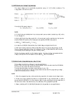
Should the threshold be over the maximum adjustable output voltage of device, a short-circuit
proof auxiliary voltage ( corresponding to the desired threshold) is to be applied on the load
terminal.
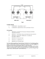
8.2 OV RESET:
After an activation of the overvoltage circuit, it remains triggered until a RESET signal occurs.
The OV RESET signal can be generated using a relay contact or a logic signal. Contact will be
established between TB 3-7 and TB 3-14. The logic signal is high-active and should have a high
level between 3.5 and 15 V and a low level under 0.8V. Load of the auxiliary signal is about
10KOhm. The connection of the logic signal is between TB4-11 (GND) and TB4-9 (active).
In case the contact is always closed or the logic signal permanently high, the overvoltage
protection circuit will be ineffective.
By power-supplies with Opt.34 the overvoltage protection can be reste with the command 'O01',
and enabled with 'O00'.
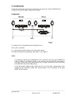
9. Series operation
Series operation of HERCULES power supplies enable a higher output voltage, however the
total output voltage should not exceed 500V. Besides it is to be noted that a voltage drop due to
the connecting lines is generated according to the current load. For an accurate regulation the
following configuration is to be respected.
Hercules 5000
Page
12
von
17
ISSUE
07/05


