


5 Installation
23
5.3.1 Installation
position
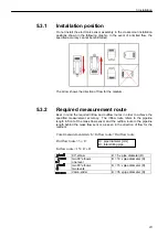
Do not install the electronic sensor assembly in the crossed-out installation
positions shown in the following graphic. In the event of a limited flow, the
specified accuracy cannot be maintained.
The arrow shows the direction of flow for the medium.
5.3.2
Required measurement route
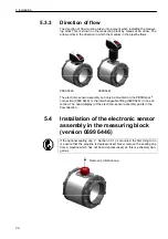
Bear in mind the required inflow and outflow routes in order to achieve the
specified measurement accuracy. The inflow route refers to the pipeline
length in front of the mass flow sensor and the outflow route to the pipeline
length behind the mass flow sensor, as seen in the direction of flow for the
medium.
route
Outflow
+
route
Inflow
=
stretch
t
measuremen
Total
D
×
=
5
route
Outflow
B
D
+
×
=
15
route
Inflow
90° elbow
B = 5 x pipe diameter (D)
two 90° elbows
one level
B = 10 x pipe diameter (D)
two 90° elbows
two levels
B = 15 x pipe diameter (D)
Valve, slider
B = 35 x pipe diameter (D)
D = pipe diameter [mm]
B = total stilling pipe
Summary of Contents for 0699 6446 Series
Page 2: ...2...
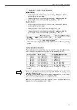
Page 7: ...1 Introduction 7 0699 6446 Standard 1 1 10 1 20 1 30 1 40 3 3 10 3 20 1 50 1 12 1 12 1 11...
Page 41: ...Notes 41...
Page 42: ...Notes 42...
Page 43: ...Notes 43...


