TESTO 0699 6446 Series Instruction Manual Download Page 19

4 Security measures 


19 

4 Security 

measures 

4.1 Intended 

purpose 

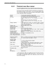
The compressed air counter is intended exclusively for use in pipe systems 
for working compressed air, provided that the calibration certificate does not 
explicitly allow using for other gases. 
 
Thanks to the design, operation in systems that are under pressure up to 
PN16 is possible. 
 
The system must be depressurized before beginning the drilling and welding 
work. 
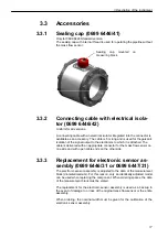
0699 6446: Before assembling or dismantling the sensor or the sealing cap 
(available as an accessory), the system status must be at zero pressure. 
 
Use which deviates from that described endangers the safety of people and 
of all of the measuring equipment and is thus not permissible. 
The manufacturer accepts no liability for damages that occur as a result of 
improper or inappropriate use or installation. 
 
To avoid damage to the instrument or health hazards, no manipulation using 
tools may occur on the measuring units that is not expressly defined in this 
operating manual. 
 
0699 6446: Changing the sensors while in operation is not possible. 
0699 6447: If all necessary operation steps are observed, changing the elec-
tronic sensor assembly while in operation is possible thanks to the inter-
changeable fitting. 
 
The compressed air counter may only be operated under the ambient condi-
tions specified in the technical data. Otherwise, inaccurate measurements 
occur or instrument malfunctions become possible. 
 
To ensure the safety of the user and the operability of the instruments, the 
commissioning steps, checks and maintenance work recommended by the 
manufacturer are to be complied with and carried out. 
 
These instructions do not contain complete detailed information for the sake 
of transparency. 
Should you require further information or should a specific problem occur 
that is not comprehensively handled in the instructions, you can request the 
required information directly from the manufacturer. 
 
Read these operating instructions before commissioning the fitting. Store 
these operating instructions in a location that is accessible for all users at all 
times. Please support us in improving these operating instructions. We are 
grateful for any ideas you may have. 


Summary of Contents for 0699 6446 Series

Page 1: ...Compressed air counter Instruction manual 0699 6446 xx Standard 0699 6447 xx With probe removal under pressure...

Page 2: ...2...

Page 3: ...ion 23 5 3 2 Required measurement route 23 5 3 3 Direction of flow 24 5 4 Installation of the electronic sensor assembly in the measuring block version 0699 6446 24 5 5 Installation of the electronic...

Page 4: ...emphasize text passages that need special attention Notes This arrow points out specifics that must be observed during operation Warning This character brings attention to text passages which if not c...

Page 5: ...er Retain the damaged goods until the matter is settled Check the scope of delivery for completeness using the shipping docu ments and your order The instrument is to be packaged for storage and trans...

Page 6: ...53 x 136 12 DN 150 Viton 3 53 x 171 05 DN 200 Viton 3 53 x 274 DN 250 Viton 3 53 x 319 2 1 12 1 10 16 16 16 16 24 24 DN 65 M12 x 20 8 8 galv DIN 931 DN 80 M12 x 22 8 8 galv DIN 931 DN 100 M12 x 25 8...

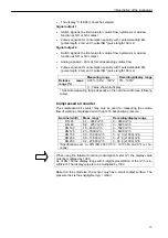
Page 7: ...1 Introduction 7 0699 6446 Standard 1 1 10 1 20 1 30 1 40 3 3 10 3 20 1 50 1 12 1 12 1 11...

Page 8: ...1 Introduction 8 0699 6447 With probe removal under pressure 1 1 10 1 30 1 40 3 3 10 3 20 1 50 1 12 1 12 1 11...

Page 9: ...d if the interchangeable fitting or the electronic sensor assembly has been opened unless this is expressly described in the instruc tion manual for maintenance purposes or if the serial numbers on th...

Page 10: ...ement principle The meas urement value of the standard volumetric flow rate is calculated based on the DIN ISO 2533 1013 hPa 15 C and 0 relative humidity The general operating conditions of compressed...

Page 11: ...range depends on the nominal width see following table Compressed air counter The compressed air counter may only be used for measuring the volume flow of working compressed air with up to 16 bar pos...

Page 12: ...9 6446 01 DN 65 124 125 70 3 2 9 185 8 13 8 3 0699 6446 02 DN 80 160 141 82 5 3 2 201 8 13 10 6 0699 6446 03 DN 100 160 165 107 1 3 6 225 8 13 12 7 0699 6446 04 DN 125 172 205 131 7 4 265 8 17 20 6 06...

Page 13: ...65 124 125 70 3 2 9 279 8 13 9 3 0699 6447 02 DN 80 160 141 82 5 3 2 295 8 13 11 6 0699 6447 03 DN 100 160 165 107 1 3 6 319 8 13 13 7 0699 6447 04 DN 125 172 205 131 7 4 359 8 17 21 6 0699 6447 05 D...

Page 14: ...m Measuring dynamics 1 300 Response time 0 1 s Pressure tight up to 16 bar positive pressure Media contact V2A 1 4301 glass passivated ceramic PEEK polyester Viton anodized aluminium Housing materials...

Page 15: ...mensions 0699 6446 Standard Item 1 Sensor display Item 2 Sensor probe component Item 3 Threaded pin Item 4 O ring Item 5 Cylindrical pin for alignment in the direction of the flow Sensor weight 428 g...

Page 16: ...emoval under pressure Item 1 Head of the electronic sensor assembly Item 2 Extension Item 3 Threaded pin Item 4 O ring Item 5 Cylindrical pin for alignment in the direction of the flow Item 6 Sensor E...

Page 17: ...ivered with an appropriate connector for the mass flow sensor on one side and with open cable ends on the other side 3 3 3 Replacement for electronic sensor as sembly 0699 6446 31 or 0699 6447 31 The...

Page 18: ...kkS calibration 0699 6447 23 Uniform for all versions The mass flow sensor receives a 2 point calibration from a DAkkS certified calibration laboratory This is documented on the electronic sensor asse...

Page 19: ...anual 0699 6446 Changing the sensors while in operation is not possible 0699 6447 If all necessary operation steps are observed changing the elec tronic sensor assembly while in operation is possible...

Page 20: ...must have read and understood these operat ing instructions and comply with the directions in these operating instruc tions Check all connections for correctness before the commissioning of the compl...

Page 21: ...nded damage to or overloading of the sealing element is impossible The groove for holding the sealing element is extensively protected during storage transportation and assembly Light scratches on the...

Page 22: ...ar antees a high level of measuring accuracy 5 3 Determining the installation point The installation point should be easily accessible and experience only low vibrations The ambient temperature may no...

Page 23: ...utflow routes in order to achieve the specified measurement accuracy The inflow route refers to the pipeline length in front of the mass flow sensor and the outflow route to the pipeline length behind...

Page 24: ...ounted on the PBCOmpac connection 0699 6446 or the interchangeable fitting 0699 6447 in one di rection The head display of the electronic sensor assembly points in the flow direction 5 4 Installation...

Page 25: ...or can only be screwed on in one position as a result of the cylin drical pin Fasten the sensor to the measuring block using a socket wrench size 36 Latch both halves of the hood back between the sens...

Page 26: ...he sensor element Turn the interchangeable fitting using only your hand into the position CLOSE This means that the interchangeable fitting seals off the interior of the pipeline Insert the electronic...

Page 27: ...instrument may only be installed by a qualified electrician Follow the national and international regulations regarding the installation of electro technical systems The voltage supply is to be laid o...

Page 28: ...connecting cable available as an option for the electrical isolation See section 3 3 2 the following line assignment is valid for the connect ing cable Wire colour Assignment Brown L 19 30 V DC volta...

Page 29: ...rement position OPEN It is essential that you have mounted the electronic sensor assembly in the interchangeable fitting properly as described in section 5 5 Slowly and evenly turn the interchangeable...

Page 30: ...interchangeable fitting is securely sealed Completely remove the union nut and remove the electronic sensor assembly by pulling it out upwards in a vertical position Take note of the sensitive sensor...

Page 31: ...asurement and evaluation functions and provides output sig nals according to the set parameters The display shows the current measurement values and the yellow LEDs show the switch status of the outpu...

Page 32: ...down The current parameter value is displayed flashing for 5 seconds After this it increases in steps by pressing singly or con tinuously by pressing and holding the button 3 Mode Enter Set Briefly p...

Page 33: ...unction normally closed NC contact Fno Window function normally open NO con tact Fnc Window function normally closed NC con tact Output signal for consumption quantity ImP Pulse value depends on the n...

Page 34: ...he following time spans can be set 1h 23h Reset after 1 23 hours 1d 6d Reset after 1 6 days 1w 8w Reset after 1 8 weeks Additionally OFF Reset after counter overflow 32 bit num ber overflow i e overfl...

Page 35: ...und the nominal value With increasing flow the output switches upon reach ing the switch point SPx If the flow decreases again the output only switches back when the return switch point rPx is reached...

Page 36: ...ge final value The output signal is between 4 and 20 mA in the set measuring range Further signals are Flow above the measuring range Output signal 20 mA Flow below the measuring range Output signal b...

Page 37: ...6 Operation 37 6 2 6 Menu overview In the menu overview S stands for the Set button and M for the Mode button on the electronic sensor assembly Nm Volume flow amount before the last reset...

Page 38: ...onic sensor as sembly version 0699 6447 The removal of the mounted electronic sensor assembly may be necessary for maintenance cleaning and calibration purposes Removing the electronic sensor assembly...

Page 39: ...Carry out a new inspection after the cleaning as required 6 6 Cleaning agents For cleaning the sensor use agents containing surfactants alkaline or wa ter soluble organic solvents e g ethanol Isoprop...

Page 40: ...our supplier 7 3 Exchange of O rings and sealing ring Keep the sealing surfaces clean during installation deinstallation Occasionally remove any surface adhesions In the event of leakage contact your...

Page 41: ...Notes 41...

Page 42: ...Notes 42...

Page 43: ...Notes 43...

Page 44: ...testo AG Postfach 1140 D 79849 Lenzkirch Testo Strasse 1 D 79853 Lenzkirch GERMANY Phone 49 0 7653 681 0 Fax 49 0 7653 681 100 Internet www testo com email info testo com 0971 6446 02 en...

Reviews: