background image

Operation 

20 

Testboy

® 

TV 225 

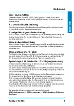
Switching on/off 

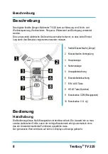
Switching on: press and hold down the ON/OFF button [7] until you hear a beep. 
Switching off: press the ON/OFF button [7]. You will hear a short beep and the display 
will go off. 

Automatic switch-off 

When there is no signal to be measured and if no buttons are pressed, the instrument will 
switch off automatically after five minutes. 

Display backlight 

Press the button with the sun symbol [5] to switch on the display backlight. Press the but-
ton again to switch the backlight off. 

Lighting of the measurement location 

Press the button with the torch symbol [6] to light up the measurement location. Press 
the button again to switch off measurement location lighting.


Reading memory (HOLD) 

To save the reading (e.g. if it is difficult to see the display at the measurement location), 
press the HOLD button [8]. The symbol "H" appears on the display. The reading is re-
tained until you press the button again.


Voltage/resistance/continuity testing 

Connect the red test lead to the "V, Ω, o)))" socket [10] and the black test lead to the 
"COM" socket [9]. 
Use the measurement probes to carry out testing parallel to the voltage source or the re-
sistance. The instrument automatically detects whether DC or AC voltage is present, or 
switches to resistance testing.  
If the resistance values are lower than 50 Ω (continuity), you will hear a continuous beep. 

The reading appears on the main display. 
Where DC voltage is detected, "DC" is displayed. The polarity of the measured voltage in 
relation to the reference point (black test lead) is also displayed. Negative polarity is indi-
cated by "-". 
Where AC voltage is present, "AC" is displayed, and the frequency of the AC voltage is 
shown in the auxiliary display. 
 
The order of automatic detection is as follows: 

AC voltage → DC voltage → AC, resistance/continuity 
 

Summary of Contents for TV 225

Page 1: ...Testboy TV 225 Version 1 0...

Page 2: ...ienungsanleitung 3 Testboy TV 225 Operating Instructions 14 Testboy TV 225 Manuel d utilisation 25 Testboy TV 225 Manual de instrucciones 36 Testboy TV 225 Manuale dell utente 47 Testboy TV 225 Bedien...

Page 3: ...ng 8 Handhabung 8 Ein Ausschalten 9 Automatische Abschaltung 9 Anzeige Hintergrundbeleuchtung 9 Messstellenbeleuchtung 9 Messwertspeicher HOLD 9 Spannungs Widerstands Durchgangsmessung 9 Wechselstromm...

Page 4: ...muss der Laserstrahl deaktiviert werden Allgemeine Sicherheitshinweise WARNUNG Aus Sicherheits und Zulassungsgr nden CE ist das eigenm chtige Umbauen und oder Ver ndern des Ger tes nicht gestattet Um...

Page 5: ...Eine andere Verwendung ist unzul ssig und kann zu Unf llen oder Zer st rung des Ger tes f hren Diese Anwendungen f hren zu einem sofortigen Er l schen jeglicher Garantie und Gew hrleistungsanspr che...

Page 6: ...mit dem Erwerb unseres Produktes haben Sie die M glichkeit das Ger t nach Ende seines Lebenszyklus an geeignete Sammelstel len f r Elektroschrott zur ckzugeben Die WEEE 2002 96 EC regelt die R cknahme...

Page 7: ...emdeinwirkung und unge ffnet an uns zur ckgesandt wird Besch digungen durch Sturz oder falsche Handhabung sind vom Garantieanspruch ausgeschlossen Bitte wenden Sie sich an Testboy GmbH Tel 49 4441 891...

Page 8: ...en 1 flexibleMessschlaufe Zange 2 Messschlaufen Verriegelung 3 Hauptanzeige 4 Nebenanzeige 5 Anzeigebeleuchtung 6 Messstellenbeleuchtung 7 EIN AUS Taste 8 HOLD Taste Speicher 9 Messbuchse COM Bezugspu...

Page 9: ...n Sie die Taste HOLD 8 Auf der Anzeige erscheint das Symbol H Der Messwert wird so lange gehalten bis die Taste erneut gedr ckt wird Spannungs Widerstands Durchgangsmessung Schlie en Sie die rote Mess...

Page 10: ...ert wird in der Hauptanzeige die Fre quenz in der Nebenanzeige dargestellt Im Falle einer gleichzeitigen Messung von Spannung ber die Messleitungen und Strom ber die Messschlaufe wird in der Hauptanze...

Page 11: ...oder des Messger tes Batteriewechsel Wenn das Batteriesymbol auf dem Display angezeigt wird sind die Batterien ver braucht und m ssen ausgetauscht werden Schalten Sie hierzu das Ger t aus und entfern...

Page 12: ...0 01 V 600 V 0 1 V Wechselspannung 1 2 3 Digits 6 V 0 001 V 60 V 0 01 V 600 V 0 1 V Wechselstrom 40 65 Hz Minimal 0 15 Ampere Maximal 3000 A effektiv 40 1000 Hz 60 A 0 01 A 3 0 5 Digits 600 A 0 1 A 30...

Page 13: ...Hz 2 0 5 Digits minimal 0 5 V bei 65 2000 Hz Eingangsimpedanz 2 M Wechselstrom 3 0 5 Digits Frequenz 0 5 2 Digits Widerstand 1 0 3 Digits Durchgang Piepton 50 Pr fstrom 1 mA Abtastfrequenz 3 Hz Arbei...

Page 14: ...19 Use 19 Switching on off 20 Automatic switch off 20 Display backlight 20 Lighting of the measurement location 20 Reading memory HOLD 20 Voltage resistance continuity testing 20 AC testing 21 Positio...

Page 15: ...ges to the instrument are not per mitted for reasons of safety and approval CE In order to ensure safe and reliable operation using the instrument you must always observe the safety instructions warni...

Page 16: ...in the immediate expiry of all guarantee and warranty claims on the part of the operator against the manufac turer Remove the batteries if the instrument is not in use for a long period of time in ord...

Page 17: ...regulates the return and recycling of waste electrical and electronics equipment As of 13 08 2005 manufactur ers of electrical and electronics equipment are obliged to take back and re cycle any elect...

Page 18: ...e warranty Please contact Testboy GmbH Tel 49 4441 89112 10 Elektrotechnische Spezialfabrik Fax 49 4441 84536 Beim Alten Flugplatz 3 D 49377 Vechta www testboy de Germany info testboy de Certificate o...

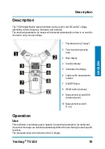
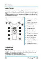
Page 19: ...Flexible test loop clamp 2 Test loop locking mecha nism 3 Main display 4 Auxiliary display 5 Illuminates the display 6 Lights up the measurement location 7 ON OFF button 8 HOLD button memory 9 Measur...

Page 20: ...urement location press the HOLD button 8 The symbol H appears on the display The reading is re tained until you press the button again Voltage resistance continuity testing Connect the red test lead t...

Page 21: ...lay and the fre quency appears on the auxiliary display When simultaneously measuring the voltage via the test leads and current via the test loop the main display shows the voltage value and the auxi...

Page 22: ...of either the test lead or the measuring instrument always applies Replacing the battery If the battery symbol is displayed the batteries are dead and need to be replaced To do this switch off the in...

Page 23: ...V 0 001 V 60 V 0 01 V 600 V 0 1 V Alternating current 40 65 Hz Min 0 15 A Max 3000 A effective 40 1000 Hz 60 A 0 01 A 3 0 5 digits 600 A 0 1 A 3000 A 1 A 65 400 Hz 60 A 0 01 A 1000 A 3 0 5 digits 600...

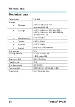
Page 24: ...65 2000 Hz Input impedance 2 M Alternating current 3 0 5 digits Frequency 0 5 2 digits Resistance 1 0 3 digits Continuity Beep 50 test current 1 mA Scan frequency 3 Hz Operating conditions 0 40 C at...

Page 25: ...he l arr t 31 Arr t automatique 31 R tro clairage de l affichage 31 clairage du point de mesure 31 M morisation des valeurs de mesure HOLD 31 Mesure de la tension de la r sistance de la continuit 31 M...

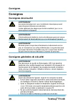
Page 26: ...personnes Consignes g n rales de s curit AVERTISSEMENT Pour des raisons de s curit et d homologation CE il est interdit de transformer et ou modifier l appareil sans autorisation Afin de garantir un f...

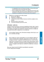
Page 27: ...uel d utilisation Toute autre utilisation est interdite et peut tre la cause d accidents ou de dommages sur l appareil Ces applications entra nent l extinction imm diate de la garantie dont b n ficie...

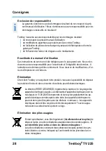
Page 28: ...erreurs limination Cher client Testboy en acqu rant notre produit vous avez la possibilit de d poser le produit en fin de vie dans un centre de collecte pour d chets lectriques La directive WEEE 2002...

Page 29: ...us est renvoy sans avoir t ouvert et ne pr sente aucune marque d intervention ext rieure Les dommages caus s par des chutes ou une mauvaise manipulation ne sont pas couverts par la garantie Veuillez v...

Page 30: ...e pince 2 Dispositif de verrouillage de la boucle de mesure 3 Affichage principal 4 Affichage secondaire 5 clairage de l affichage 6 clairage du point de mesure 7 Bouton MARCHE ARR T 8 Bouton HOLD m m...

Page 31: ...sur le lieu de mesure Le symbole H apparait sur l affi chage La valeur de mesure est conserv e jusqu ce que le bouton soit nouveau enfonc Mesure de la tension de la r sistance de la continuit Raccord...

Page 32: ...ure apparait dans l affichage principal et la fr quence dans l affichage secondaire En cas de mesure simultan e de la tension via des lignes de mesure et du courant via la boucle de mesure l affichage...

Page 33: ...c est toujours la plus petite cat gorie soit de la ligne de mesure soit de l instrument de mesure qui est valable Remplacement des piles Lorsque le symbole de la batterie appara t l cran les piles son...

Page 34: ...V 0 01 V 600 V 0 1 V Tension alternative 1 2 3 digits 6 V 0 001 V 60 V 0 01 V 600 V 0 1 V Courant alternatif 40 65 Hz Min 0 15 Amp re Max 3000 A eff 40 1000 Hz 60 A 0 01 A 3 0 5 digits 600 A 0 1 A 30...

Page 35: ...Hz Imp dance d entr e 2 M Courant alternatif 3 0 5 digits Fr quence 0 5 2 digits R sistance 1 0 3 digits Continuit Signal sonore 50 courant de contr le 1 mA Fr quence de balayage 3 Hz Environnement d...

Page 36: ...sconexi n autom tica 42 Iluminaci n de fondo del indicador 42 Iluminaci n de los puntos de medici n 42 Memoria de valores de medici n HOLD 42 Medici n de tensi n de resistencia y de continuidad 42 Med...

Page 37: ...er Indicaciones generales de seguridad ADVERTENCIA Por motivos de seguridad y homologaci n CE no est permitido transformar ni realizar modificaciones por cuenta propia en el instrumento Con el fin de...

Page 38: ...uier otro uso Este podr a causar accidentes o la destrucci n del instrumento Estos usos resultar n en la anulaci n inmediata de cualquier derecho por garant a del operario frente al fabricante Para pr...

Page 39: ...ro producto tiene la posibilidad de una vez finalizada su vida til devolver el instrumento a los puntos de recogida adecuados para chatarra el ctrica La Directiva RAEE 2002 96 CE regula la recogida y...

Page 40: ...do ni abierto Los da os por ca da o por manejo err neo quedan excluidos de la garant a P ngase en contacto con Testboy GmbH Tel 49 4441 89112 10 Fabricante especial electrot cnico Fax 49 4441 84536 Be...

Page 41: ...flexible pinza 2 Bloqueo del lazo de medici n 3 Pantalla principal 4 Indicaci n auxiliar 5 Iluminaci n del indicador 6 Iluminaci n de los puntos de medici n 7 Tecla ON OFF 8 Tecla HOLD memoria 9 Mang...

Page 42: ...peor pulse la tecla HOLD 8 En la pantalla aparece el s mbolo H El valor de medici n permanecer hasta que se pulse de nuevo la tecla Medici n de tensi n de resistencia y de continuidad Conecte el cabl...

Page 43: ...antalla principal la frecuencia en la pantalla secundaria En caso de medici n simult nea de tensi n mediante los cables de medici n y corriente mediante el lazo de medici n en la pantalla principal se...

Page 44: ...rige siempre la categor a m s baja bien del cable de medici n o del instrumento de medici n Cambio de pilas Si el s mbolo de bater a aparece en la pantalla las bater as est n gastadas y deben reempla...

Page 45: ...01 V 600 V 0 1 V Tensi n alterna 1 2 3 d gitos 6 V 0 001 V 60 V 0 01 V 600 V 0 1 V Corriente alterna 40 65 Hz M nima 0 15 amperios M xima 3000 A efectiva 40 1000 Hz 60 A 0 01 A 3 0 5 d gitos 600 A 0 1...

Page 46: ...Hz Impedancia de entrada 2 M Corriente alterna 3 0 5 d gitos Frecuencia 0 5 2 d gitos Resistencia 1 0 3 d gitos Continuidad Pitido 50 Corriente de control 1 mA Frecuencia de exploraci n 3 Hz Entorno...

Page 47: ...53 Spegnimento automatico 53 Retroilluminazione del display 53 Illuminazione del punto di misura 53 Memorizzazione del valore di misura HOLD 53 Misura di tensione resistenza e continuit 53 Misura dell...

Page 48: ...ivi di sicurezza e di omologazione CE non sono ammesse modifi che e o trasformazioni arbitrarie dello strumento Per garantire un funziona mento sicuro dello strumento assolutamente necessario osservar...

Page 49: ...mentare e pu cau sare infortuni o il danneggiamento irreparabile dello strumento Simili usi causano un immediato annullamento della garanzia concessa dal produttore all utente Se lo strumento non vien...

Page 50: ...ento al termine del suo ciclo di vita ai centri di raccolta per rifiuti elettronici La normativa RAEE 2002 96 CE regola la restituzione e il riciclaggio degli apparecchi elettronici Dal 13 8 2005 i pr...

Page 51: ...stituito intatto e senza interventi esterni Sono esclusi dalla garanzia i danni derivanti dalla caduta o da un uso im proprio dello strumento Rivolgersi a Testboy GmbH Tel 49 4441 89112 10 Elektrotech...

Page 52: ...di misura flessibile 2 Meccanismo di bloccaggio della pinza 3 Display principale 4 Display secondario 5 Retroilluminazione del display 6 Illuminazione del punto di misura 7 Tasto ON OFF 8 Tasto HOLD...

Page 53: ...lore di misura rimane congelato sino a quando il tasto viene premuto per la seconda volta Misura di tensione resistenza e continuit Collegare il cavo di misura rosso alla porta V o 10 e il cavo di mis...

Page 54: ...requenza su quello secondario In caso di una misura contemporanea della tensione tramite i cavi di misura e della cor rente tramite la pinza flessibile sul display principale viene visualizzato il val...

Page 55: ...e delle batterie Quando sul display compare il simbolo significa che le batterie si stanno esauren do e devono essere sostituite Per sostituirle spegnere lo strumento e scollegare eventualmente i cavi...

Page 56: ...3 digit 6 V 0 001 V 60 V 0 01 V 600 V 0 1 V Corrente alternata 40 65 Hz Min 0 15 Ampere Max 3000 A effettivi 40 1000 Hz 60 A 0 01 A 3 0 5 digit 600 A 0 1 A 3000 A 1 A 65 400 Hz 60 A 0 01 A 1000 A 3 0...

Page 57: ...V a 65 2000 Hz Impedenza d ingresso 2 M Corrente alternata 3 0 5 digit Frequenza 0 5 2 digit Resistenza 1 0 3 digit Continuit Segnale acustico 50 corrente di prova 1 mA Frequenza di campionamento 3 H...

Page 58: ...ring 63 In Uitschakelen 64 Automatische uitschakeling 64 Achtergrondverlichting van het display 64 Verlichting van meetpunten 64 Meetwaardengeheugen HOLD 64 Spannings Weerstands Doorgangsmeting 64 Wis...

Page 59: ...ensen moet de laser straal uitgeschakeld worden Algemene veiligheidsinstructies WAARSCHUWING Om redenen van veiligheid en toelating CE is het eigenmachtige om bouwen en of veranderen van het instrumen...

Page 60: ...r gebruik is niet toegelaten en kan ongevallen of onherstelbare beschadiging van het instrument tot gevolg hebben Deze toepassingen hebben tot gevolg dat elk recht op garantie en schadevergoeding van...

Page 61: ...e Testboy klant met de aankoop van ons product heeft u de mogelijkheid om het instrument na afloop van zijn levensduur in te leveren op inzamelpunten voor elektrisch schroot WEEE 2002 96 EC regelt de...

Page 62: ...invloeden en ongeopend aan ons wordt teruggestuurd Beschadigingen door een val of verkeer de hantering zijn uitgesloten van het recht op garantie Gelieve u te wenden tot Testboy GmbH Tel 49 4441 8911...

Page 63: ...1 flexibele meetlus tang 2 vergrendeling van de meetlus 3 hoofdindicatie 4 hulpindicatie 5 displayverlichting 6 verlichting van meetpunten 7 AAN UIT toets 8 HOLD toets geheugen 9 meetbus COM referent...

Page 64: ...en drukt u op de toets HOLD 8 Op het display verschijnt het symbool H De meetwaarde wordt zo lang bijgehouden tot de toets opnieuw wordt ingedrukt Spannings Weerstands Doorgangsmeting Sluit de rode me...

Page 65: ...de hoofdin dicatie de frequentie in de hulpindicatie In het geval van een gelijktijdige meting van spanning via de meetleidingen en stroom via de meetlus wordt in de hoofdindicatie de spanning en in d...

Page 66: ...of van het meetin strument Batterijvervanging Wanneer het batterijsymbool wordt weergegeven op het display dan zijn de batte rijen opgebruikt en moeten deze worden vervangen Schakel hiervoor het inst...

Page 67: ...V 0 01 V 600 V 0 1 V Wisselspanning 1 2 3 digits 6 V 0 001 V 60 V 0 01 V 600 V 0 1 V Wisselstroom 40 65 Hz Minimaal 0 15 amp re Maximaal 3000 A effectief 40 1000 Hz 60 A 0 01 A 3 0 5 digits 600 A 0 1...

Page 68: ...2 0 5 digits minimaal 0 5 V bei 65 2000 Hz Ingangsimpedantie 2 M Wisselstroom 3 0 5 digits Frequentie 0 5 2 digits Weerstand 1 0 3 digits Doorgang Pieptoon 50 proefstroom 1 mA Aftastfrequentie 3 Hz We...

Page 69: ......
Page 70: ...Testboy GmbH Tel 49 4441 89112 10 Elektrotechnische Spezialfabrik Fax 49 4441 84536 Beim Alten Flugplatz 3 D 49377 Vechta www testboy de Germany info testboy de...

Reviews: