


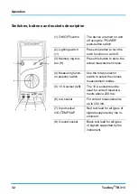


Operation
38 Testboy
®
TB 313
Diode test
With the selector switch set to "
/
◦
))". Insert the black test lead into the
‘COM’ socket and the red test lead into the V/
Ω
/TEMP/CAP socket. Using
the test probes, touch the test points of the test object. Red test lead = an-
ode, black test lead = cathode. The forward voltage drop is displayed.
Measurement range
Resolution Display
1 mV
Forward voltage
-Forward current: approx. 25 µA, reverse voltage: approx. 2.8 V.
Continuity testing
With the selector switch set to "
/
◦
))". Insert the black test lead into the
‘COM’ socket and the red test lead into the V/
Ω
/TEMP/CAP socket. Using
the test probes, touch the test points of the test circuit. An acoustic signal is
emitted if a resistance under 70
Ω
is measured.
Important: Isolate from the power supply and discharge capacitors
in the circuit to be measured.
Measurement range
Function
◦
))
The integrated buzzer signals up to a resis-
tance of 70
Ω
-Measuring voltage: approx. 2.8 V.
Summary of Contents for TB 313
Page 1: ...Testboy TB 313 Version 1 0 ...
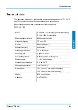
Page 22: ...Technische Daten 22 Testboy TB 313 ...
Page 42: ...Technical data 42 Testboy TB 313 ...
Page 62: ...Caractéristiques techniques 62 Testboy TB 313 ...
Page 82: ...Dati tecnici 82 Testboy TB 313 ...
Page 102: ...Datos técnicos 102 Testboy TB 313 ...
Page 122: ...Dados técnicos 122 Testboy TB 313 ...
Page 142: ...Technische gegevens 142 Testboy TB 313 ...
Page 143: ......


