


7
USER MANUAL
NEOLINE
PLUS
�
1/1
�
1-3 kVA
�
ONLINE UPS
7
2-2. Προγραμματισμός του UPS
Βήμα 1: UPS σύνδεση εισόδου
Συνδέστε το UPS σε μια διπολική, με τρία σύρματα, γειωμένη πρίζα μόνο. Αποφεύγετε να χρησιμοποιείτε
καλώδια επέκτασης. Το καλώδιο ρεύματος σας παρέχεται μέσα στη συσκευασία του UPS.
Βήμα 2: UPS σύνδεση εξόδου
1.
Για εξόδους τύπου πρίζας, απλά συνδέστε τις συσκευές στις υποδοχές.
2.
Για εισόδους ή εξόδους τύπου ακροδέκτη, παρακαλώ ακολουθήστε τα παρακάτω βήματα για τη
διαμόρφωση της καλωδίωσης:
α) Μετακινήστε το μικρό κάλυμμα του μπλοκ ακροδεκτών
β) Σας συνιστούμε να χρησιμοποιήσετε καλώδια ρεύματος διατομής 2.5mm2
γ) Με την ολοκλήρωση της διαμόρφωσης καλωδίωσης, παρακαλώ ελέγξτε εάν τα καλώδια
είναι ασφαλώς επικολλημένα.
δ) Τοποθετήστε το μικρό κάλυμμα πίσω στον πίνακα που βρίσκεται στο πίσω μέρος.
Βήμα 3: Σύνδεση επικοινωνίας Θύρα επικοινωνίας:
Για να επιτρέψετε σε αφύλακτο UPS κλείσιμο/εκκίνηση και παρακολούθηση κατάστασης, συνδέστε τα
καλώδια επικοινωνίας ένα στο τέλος της θύρας USB/RS-232 και το άλλο στη θύρα επικοινωνίας του
PC σας. Με το εγκατεστημένο λογισμικό παρακολούθησης, μπορείτε να προγραμματίσετε το κλείσιμο
εκκίνηση του UPS και να παρακολουθείτε την κατάσταση του UPS μέσω του PC.
Το UPS είναι εξοπλισμένο με έξυπνη θύρα κατάλληλη είτε για SNMP ή AS400 κάρτα. Κατά την
εγκατάσταση είτε της SNMP ή της AS400 κάρτας στο UPS, αυτό θα παρέχει προηγμένη εποικοινωνία
και επιλογές παρακολούθησης.
Σημείωση:
Οι θύρες USB και RS-232 δεν μπορούν να λειτουργούν συγχρόνως.
Βήμα 4: Εκκίνηση του UPS
Πιέστε το κουμπί ON/Mute στον μπροστινό πίνακα για 2 δευτερόλεπτα για να δωσετε ενέργεια στο UPS.
Σημείωση:
Η μπαταρία φορτιζει πλήρως κατά τη διάρκεια των πέντε πρώτων ωρών κανονικής
λειτουργίας. Μην περιμένετε πλήρη απόδοση μπαταρίας κατά τη διάρκεια αυτής της αρχικής περιόδου
φόρτισης.
Βήμα 5: Εγκατάσταση λογισμικού
Για βέλτιστη προστασία του συστήματος του υπολογιστή σας, εγκαταστήστε το λογισμικό
παρακολούθησης του UPS για να διαμορφώσετε το κλείσιμο του UPS. Μπορείτε να εισάγετε το CD
που σας παρέχεται μέσα στο CD-ROM για να εγκαταστήσετε το λογισμικό παρακολούθησης. Εάν όχι,
παρακαλώ ακολουθήστε τα παρακάτω βήματα για να κατεβάσετε και να εγκαταστήσετε το λογισμικό
παρακολούθησης από το διαδίκτυο:
1.
Πηγαίντε στην ηλεκτρονική διεύθυνση http://www.power-software-download.com
2.
Πατήστε στο εικονίδιο λογισμικό ViewPower και μετά επιλέξτε το απαιτούμενο για εσάς λειτουργικό
σύστημα για να κατεβάσετε το λογισμικό.
3.
Ακολουθήστε τις οδηγίες στην οθόνη για να εγκαταστήσετε το λογισμικό.
4.
Όταν γίνει επανεκκίνηση του υπολογιστή σας, το λογισμικό παρακολούθησης θα εμφανιστεί σαν
ένα πορτοκαλί εικονίδιο βελάκι που βρίσκεται στο δίσκο του συστήματος, κοντά στο ρολόι.
Θύρα USB
Θύρα RS-232
Έξυπνη θύρα
8
Step 3: UPS output connection
For socket-type outputs, simply connect devices to the outlets.
For terminal-type input or outputs, please follow below steps for the wiring configuration:
a) Remove the small cover of the terminal block
b) Suggest using AWG14 or 2.1mm
2
power cords for 3KVA (208/220/230/240VAC models).
Suggest using AWG12-10 or 3.3mm
2
-5.3mm
2
power cords for 3KVA
(110/115/120/127VAC models). Please also install a circuit breaker (40A) between the
mains and AC input of UPS in 3KVA (110/115/120127VAC models) for safety operation.
c) Upon completion of the wiring configuration, please check whether the wires are
securely affixed.
d) Put the small cover back to the rear panel.
Step 4: Communication connection
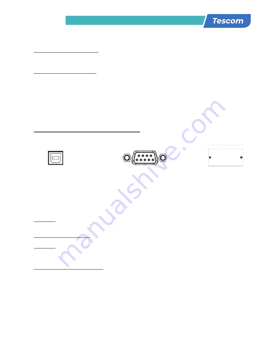
Communication port:
USB port RS-232 port
Intelligent slot
To allow for unattended UPS shutdown/start-up and status monitoring, connect the
communication cable one end to the USB/RS-232 port and the other to the communication port
of your PC. With the monitoring software installed, you can schedule UPS shutdown/start-up and
monitor UPS status through PC.
The UPS is equipped with intelligent slot perfect for either SNMP or AS400 card. When installing
either SNMP or AS400 card in the UPS, it will provide advanced communication and monitoring
options.
PS. USB port and RS-232 port can’t work at the same time.
Step 5: Turn on the UPS
Press the ON/Mute button on the front panel for two seconds to power on the UPS.
Note: The battery charges fully during the first five hours of normal operation. Do not expect
full battery run capability during this initial charge period.
Step 6: Install software
For optimal computer system protection, install UPS monitoring software to fully configure UPS
shutdown. You may insert provided CD into CD-ROM to install the monitoring software. If not,
please follow steps below to download and install monitoring software from the internet:
1. Go to the website http://www.power-software-download.com
2. Click ViewPower software icon and then choose your required OS to download the software.
3. Follow the on-screen instructions to install the software.
4. When your computer restarts, the monitoring software will appear as an orange plug icon
located in the system tray, near the clock.
8
Step 3: UPS output connection
For socket-type outputs, simply connect devices to the outlets.
For terminal-type input or outputs, please follow below steps for the wiring configuration:
a) Remove the small cover of the terminal block
b) Suggest using AWG14 or 2.1mm
2
power cords for 3KVA (208/220/230/240VAC models).
Suggest using AWG12-10 or 3.3mm
2
-5.3mm
2
power cords for 3KVA
(110/115/120/127VAC models). Please also install a circuit breaker (40A) between the
mains and AC input of UPS in 3KVA (110/115/120127VAC models) for safety operation.
c) Upon completion of the wiring configuration, please check whether the wires are
securely affixed.
d) Put the small cover back to the rear panel.
Step 4: Communication connection
Communication port:
USB port RS-232 port
Intelligent slot
To allow for unattended UPS shutdown/start-up and status monitoring, connect the
communication cable one end to the USB/RS-232 port and the other to the communication port
of your PC. With the monitoring software installed, you can schedule UPS shutdown/start-up and
monitor UPS status through PC.
The UPS is equipped with intelligent slot perfect for either SNMP or AS400 card. When installing
either SNMP or AS400 card in the UPS, it will provide advanced communication and monitoring
options.
PS. USB port and RS-232 port can’t work at the same time.
Step 5: Turn on the UPS
Press the ON/Mute button on the front panel for two seconds to power on the UPS.
Note: The battery charges fully during the first five hours of normal operation. Do not expect
full battery run capability during this initial charge period.
Step 6: Install software
For optimal computer system protection, install UPS monitoring software to fully configure UPS
shutdown. You may insert provided CD into CD-ROM to install the monitoring software. If not,
please follow steps below to download and install monitoring software from the internet:
1. Go to the website http://www.power-software-download.com
2. Click ViewPower software icon and then choose your required OS to download the software.
3. Follow the on-screen instructions to install the software.
4. When your computer restarts, the monitoring software will appear as an orange plug icon
located in the system tray, near the clock.
Summary of Contents for NEOLINE PLUS 1102ST
Page 38: ......


