


26
INSTALLATION
Installation and Servicing
Blue
Handle
Filling
Loop
CH Flow
DHW
Outlet
Gas
Supply
DHW
Inlet
CH
Return
Safety
Drain
Valve
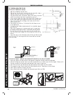
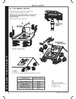
24 CONNECTIONS & FILLING
IMPORTANT
- when filling:
When filling, there may be a slight water leak from the air vent
therefore electrical connections must be protected.
Note.
The domestic hot water flow rate is
automatically regulated to a maximum:
26/35 - 14.5 l/m (0.87 m
3
/hr)
31/35 - 14.5 l/m (0.87 m
3
/hr)
1.
Ensure Filling Loop is connected
2.
Ensure dust cap on auto air vent is slackened off (refer to
Frame 58).
3.
Check the isolation handle on water connections are in the
open position.
4.
Check the DHW inlet valve (blue handle) is in the DHW
position.
5.
Slowly open the DHW inlet valve (blue handle) towards the
filling position until pressure gauge reads between 1 to 1.5
bar.
6.
Once pressure gauge dial reads between 1 - 1.5 bar turn the
DHW Valve back to the closed position.
FILLING
Note. Fully open all DHW taps and ensure water is
flowing freely. Once satisfied close all taps.
4
5
DHW inlet valve in the DHW
position
DHW inlet valve in the filling
position
3G9705
Safety Valve
Drain Connection
15mm elbow
or fittings
(not supplied)
Pressure Relief Valve
Drain Pipe
NOTES.
Ensure all boss blanking plugs are removed before connecting hardware. Each
connector must be fitted to the correct boss as shown in the picture. Each
connection must be fitted Each pack within the hardware box is colour coded to
match the positions indicated on the label fitted to the bottom of the boiler
Ensure each union is fitted with fibre seals provided.
Do not subject any of the connectors to heat as the seals may be damaged.
WATER CONNECTIONS CH
1.
Fit the CH flow service connector (green pack) and copper
tail provided in the hardware pack to the threaded boss
connection provided at the lower rear of the boiler.
2.
Connect the CH rtn. connector and copper tail (grey pack).
GAS CONNECTION
IMPORTANT.
The gas connection is sealed with a non-metallic
blue fibre washer, which must not be overheated when making
capillary connections. Refer to Frame 1 for details of the position
of the gas connection.
For additional gas supply info refer to “Gas Supply” on page 8.
SAFETY VALVE DRAIN
The safety valve connection, located at the bottom right-hand
side of the boiler, comprises a 15mm diameter stub pipe.
The Installer to provide a compression joint on the end of the
stub pipe. This assists with pipe removal when servicing.
The discharge pipe should be positioned so that the discharge
of water or steam cannot create a hazard to the occupants of
the premises or damage the electrical components and wiring.
WATER CONNECTIONS DHW
1.
Fit the DHW inlet service valve (blue handle) and copper tail
to the threaded boss connection shown below ensuring the
seal provided is correctly located.
2.
Fit the DHW outlet pipe tail to DHW outlet connection,
ensuring the seal provided is correctly located.
3.
Fit the filling loop provided between the DHW inlet valve and
the CH return connector.
INST
ALLA
TION


