background image

                                                                                   XM429-V1.2-C 

57

picture: 


10. INSTRUCTIONS ON USE:   


DMX channel´s functions and their values (57 DMX channels): 

Mode/Channel Value 

Function 

St Ba Ex 


Cyan Color   : 

1 1 1 

0-255 

Cyan (0-white, 255-100% Cyan)   


Cyan Color Fine    : 


 2 

0-255 Cyan 

Fine 


Magenta Color : 

2 2 3 

0-255 Magenta 

(0-white, 

255-100% 

magenta) 


Magenta Color Fine : 


 4 

0-255 Magenta 

Fine 


Yellow Color  : 

3 3 9 

0-255 

Yellow (0-white, 255-100% Yellow)   


Yellow Color Fine : 


 10 

0-255 Yellow 

Fine 


CTO Color    : 

4 4 11 

0-255 

CTO (0-white, 255-100% CTO)   


CTO Color Fine : 


 12 

0-255 CTO 

Fine 


PAN Movement 8bit : 

5 5 5 

0-255 Pan 

Movement 


TILT Movement 8bit : 

6 6 6 

0-255 Tilt 

Movement 


Speed Pan/Tilt movement: 

7 7 7 

0-225 

Max to min speed 

Summary of Contents for V2000P-R

Page 1: ...XM429 V1 2 C 31 MOVING HEAD USER MANUAL V2000P R KEEP THIS MANUAL FOR FUTURE NEEDS ...

Page 2: ...5 One warranty card and certification Please check carefully that there is no damage caused by transportation Should there be any consult your dealer and don t install this device 1 FEATURES 3 Control channel modes 34 36 57channels Pan tilt movement 16 bit resolution For smooth and precise resolution Pan 540 630 optional Tilt 245 movement High speed of pan tilt movement speed of pan tilt movement ...

Page 3: ...y for Display 7 User Assignable Program Presets Internal Program Edit and save programs to the incorporated EPROM Maximum of 64 scenes Software upload by optional accessory via DMX line Editable program Edit and save the program to inside EEPROM via the control board or external controller up to 250 scenes can be saved and then can be run in Stand Alone or sound activated 2 FIXTURE OVERVIEW 1 Proj...

Page 4: ...wn effective degree such as cracked and gashed it must be replaced The electric connection must carry out by qualified person Make sure that the available voltage is not higher than stated at the end of this manual Make sure the power cord is never crimped or damaged by sharp edges If this would be the case replacement of the cable must be done by an authorized dealer Always disconnect from the ma...

Page 5: ...oles correctly Operate the device only after having familiarized with its functions Do not permit operation by persons not qualified for operating the device Most damages are the result of unprofessional operation Please use the original packaging if the device is to be transported For safety reasons please be aware that all modifications on the device are forbidden If this device will be operated...

Page 6: ...mp is not a hot restrike type you must wait for approximately 15 minutes after having turned off the lamp before you can turn it back on again Do not operate this device with open cover 4 2 Mounting the device The applicable temperature for the lighting is between 25 C to 45 C Do not use the lighting under or above the temperature The installation of the effect has to be built and constructed in a...

Page 7: ...times the device s weight Connect the fixture to the mains with the power plug Installation via the Omega holders a Fixed the clamp on the bracket by tighten up the M12 screw on the bracket to the Ф13 hole in the middle of the bracket b Insert the quick lock fasteners of the first Omega holder into the respective holes on the bottom of the device Tighten the quick lock fasteners fully clockwise c ...

Page 8: ...o prevent accidental damage and or injury in the event the clamp fails Overhead mounting requires extensive experience including amongst others calculating working load limits a fine knowledge of the installation material being used and periodic safety inspection of all installation material and the fixture If you lack these qualifications do not attempt the installation yourself Improper installa...

Page 9: ...m below Starting address 1 Starting address 37 Starting address 73 6 DMX 512 connection with DMX terminator For installations where the DMX cable has to run a long distance or is in an electrically noisy environment such as in a discotheque it is recommended to use a DMX terminator This helps in preventing corruption of the digital control signal by electrical noise The DMX terminator is simply an...

Page 10: ...ess transmitter and the fixtures with wireless receiver 2 Message from the LED indicator 1 Rapid flashing red Green logging in to a transmitter 2 Slow flashing Red Green Logged on a transmitter and the DMX line is idle No DMX is connected to transmitter 3 Solid Green Logged on to a transmitter and receiving DMX data 4 Solid Red Not logged on to a transmitter free 3 WDMX in the menu of the fixture ...

Page 11: ...All the red green LEDs on the receiver fixtures will turn to Solid red to indicate that the receivers are unassigned and removed from the transmitter T1 c Press and hold the configuration button on the T2 less then less than 3 second the fixtures will connect with the T2 PS 1 Please log the receivers out from the transmitter after every job so that the receivers are in free un assigned state and r...

Page 12: ... Head Temperature XXX Temperature in the head Information Software Version Verx x Software version of each IC Lamp Control Lamp On or Off Automatic La On Lamp On Via DMX Lamp Off Via DMX Lamp On at Temp Lamp Off at Temp ON OFF ON OFF ON OFF ON OFF 20 79 45 68 174 113 80 139 130 176 282 266 Lamp on off Lamp on off when Power on Lamp on via DMX Lamp off via DMX Lamp restart at temp Lamp off at temp ...

Page 13: ...e User Mode A User Mode B User Mode C User s mode to change channel numbers Users Mode Set Edit User Mode Max Channel PAN Max Channel XX PAN CH01 Preset User modes Select Programs Auto Pro Part 1 Auto Pro Part 2 Auto Pro Part 3 Program 1 10 Program 1 Program 1 10 Program 2 Program 1 10 Program 3 Select programs to be run Edit Program Program 1 Program 10 Program Test Step 01 SCxxx Step 64 SCxxx ST...

Page 14: ...set the number of steps under Edit program You can edit the individual scenes under Edit scenes With this function you can run the individual scenes either automatically i e with the adjusted Step Time 1 Access the main menu 2 Tap the Up Down button until Auto Program is displayed 3 Press ENTER the display will show Auto Program 4 Tap the Up Down button the display will show Master1 Alone 5 Press ...

Page 15: ...ours 1 Tap MODE ESC button access the main menu Tap the Up Down button until Information is displayed Press ENTER the display will show Information Tap the Up Down button until the display will show Time Information Press ENTER the display will show Time Information 2 Press Up Down the display will show Last Run Hours 3 Press ENTER the display will show Last Run Hours 4 The display will show XXXX ...

Page 16: ...irm 1 Tap MODE ESC button access the main menu Tap the Up Down button until Information is displayed Press ENTER the display will show Information Tap the Up Down button until the display will show Time Information Press ENTER the display will show Time Information 2 Press Up Down the display will show Clear Last Run 3 At Timer Password menu input a correct password press ENTER the display will sh...

Page 17: ...til Information is displayed Press ENTER the display will show Information 2 Press Up Down the display will show Software version 3 Press ENTER the display will show Software version 4 The display show Ver 1 0 5 Press ENTER to confirm or press MODE ESC to return to the main menu 9 3 LAMP CONTROL When the real temperature around the lamp is higher than the preset value the lamp will be shut down in...

Page 18: ... button access the main menu Tap the Up Down button until Lamp Control is displayed Press ENTER the display will show Lamp Control Tap the Up Down button until the display will show Lamp On Via DMX Press ENTER the display will show Lamp On Via DMX 2 Press Up Down the display will show OFF or ON 3 Press ENTER to confirm or press MODE ESC to return to the main menu 9 3 4 Lamp off via external contro...

Page 19: ...s via DMX With this function you can adjust the desired DMX address via an external controller 1 Tap MODE ESC button access the main menu Tap the Up Down button until Personality is displayed Press ENTER the display will show Personality Tap the Up Down button until the display will show Status setting Press ENTER the display will show Status setting 2 Press Up Down the display will show Address v...

Page 20: ...ee With this function you can select pan degree for 630 or 540 1 Tap MODE ESC button access the main menu Tap the Up Down button until Personality is displayed Press ENTER the display will show Personality Tap the Up Down button until the display will show Status setting Press ENTER the display will show Status setting 2 Press Up Down the display will show Pan Degree 3 Press ENTER the display will...

Page 21: ...tay without DMX signal for 15 mins Factory default And the fixture will be reset before working once it receive DMX signal again 1 Tap MODE ESC button access the main menu Tap the Up Down button until Personality is displayed Press ENTER the display will show Personality Tap the Up Down button until the display will show Status setting Press ENTER the display will show Status setting 2 Press Up Do...

Page 22: ...r press MODE ESC to return to the main menu 9 4 3 Fans Control With this function you can set the speed of the running fans The selections have Auto high and low 1 Tap MODE ESC button access the main menu Tap the Up Down button until Personality is displayed Press ENTER the display will show Personality 2 Press Up Down the display will show Fans Control 3 Press ENTER the display will show Fans Con...

Page 23: ...eless data transmission W DMX If you wish to de activate W DMX control you can select the function De activate WDMX by turning the encoder With the function rest you can log out the projector from the wireless sender 1 Tap MODE ESC button access the main menu Tap the Up Down button until Personality is displayed Press ENTER the display will show Personality 2 Press Up Down the display will show Wi...

Page 24: ...amp adjustment 1 Tap MODE ESC button access the main menu Tap the Up Down button until Effect Adjust is displayed Press ENTER the display will show Effect Adjust 2 Press Up Down the display will show Manual control 3 Press ENTER the display will show Manual control 4 The display show PAN XXX 5 Press ENTER to confirm or press MODE ESC to return to the main menu 9 6 3 Calibrate values With this func...

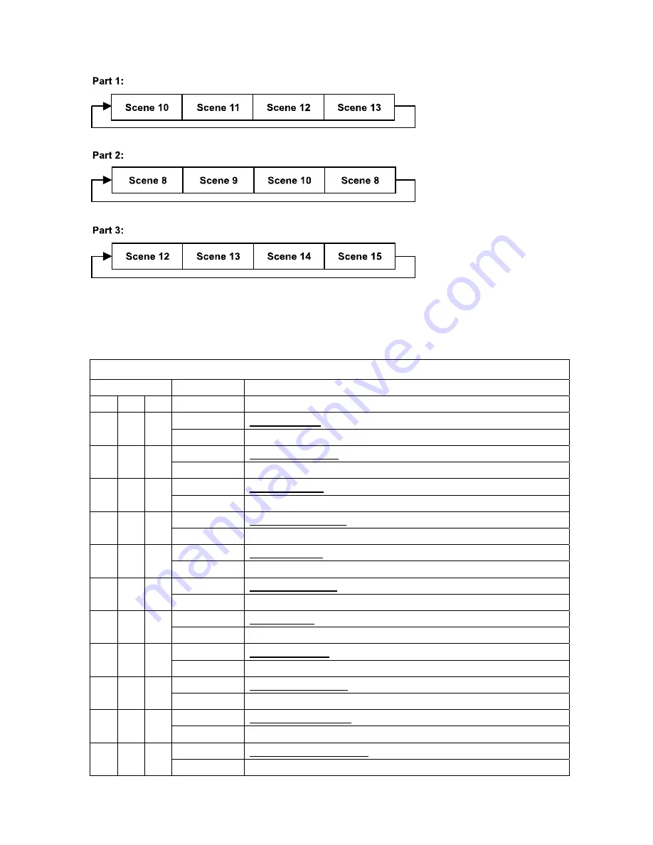
Page 25: ...es at your controller they will automatically be transmitted to the moving head Excursion A Master unit can send up to 3 different data groups to the Slave units i e a Master unit can start 3 different Slave units which run 3 different programs The Master unit sends the 3 program parts in a continuous loop The Slave unit receives data from the Master unit according to the group which the Slave uni...

Page 26: ...Select Edit program by turning the encoder Press the Enter button to confirm Select Edit program by turning the encoder Press the Enter button to confirm Turn the encoder to select the desired program With this function you can edit specific scenes into a specific program Press the Enter button to confirm Press the MODE ESC button in order to return to the main menu 5 Automatic Scene Recording Sel...

Page 27: ...n Fine Magenta Color 2 2 3 0 255 Magenta 0 white 255 100 magenta Magenta Color Fine 4 0 255 Magenta Fine Yellow Color 3 3 9 0 255 Yellow 0 white 255 100 Yellow Yellow Color Fine 10 0 255 Yellow Fine CTO Color 4 4 11 0 255 CTO 0 white 255 100 CTO CTO Color Fine 12 0 255 CTO Fine PAN Movement 8bit 5 5 5 0 255 Pan Movement TILT Movement 8bit 6 6 6 0 255 Tilt Movement Speed Pan Tilt movement 7 7 7 0 2...

Page 28: ... position Fine Rotating gobos cont rotation 1 0 9 Open 10 19 Rot gobo 1 20 29 Rot gobo 2 30 39 Rot gobo 3 40 49 Rot gobo 4 50 59 Rot gobo 5 60 69 Rot gobo 6 70 89 Gobo 1 shake slow to fast 90 109 Gobo 2 shake slow to fast 110 129 Gobo 3 shake slow to fast 130 149 Gobo 4 shake slow to fast 150 169 Gobo 5 shake slow to fast 170 189 Gobo 6 shake slow to fast 190 221 Gobo wheel rotation forwards from ...

Page 29: ...ke slow to fast 190 221 Gobo wheel rotation forwards from fast to slow 222 223 No rotation 12 12 18 224 255 Gobo wheel rotation f backwards from slow to fast Fixed gobo indexing Fine 19 0 255 Fixed gobo Fine indexing Rotating prism Prism Gobo macros 0 63 Open 64 127 3 Facet Prism 128 135 Macro 1 136 143 Macro 2 144 151 Macro 3 152 159 Macro 4 160 167 Macro 5 168 175 Macro 6 176 183 Macro 7 184 191...
Page 30: ...t slow to fast 96 127 No function shutter open 128 159 Pulse effect in sequences 160 191 No function shutter open 192 223 Random strobe effect slow to fast 17 17 27 224 255 No function shutter open Dimmer intensity 18 18 28 0 255 Intensity 0 to 100 Fine Dimmer intensity 29 0 255 Dimmer intensity fine Iris 0 191 Max diameter to Min diameter 192 223 Pulse opening fast to slow 19 19 30 224 255 Pulse ...

Page 31: ...Macro23 192 199 Macro24 200 207 Macro25 208 215 Macro26 216 223 Macro27 224 231 Macro28 232 239 Macro29 240 247 Macro30 248 255 Random CMY Top Blade 23 23 35 0 255 Open to Close Top Blade Fine 36 0 255 Open to Close Fine Top Blade Rotation 24 24 37 0 255 Top Blade Rotation Top Blade Rotation Fine 38 0 255 Top Blade Rotation Fine Bottom Blade 25 25 39 0 255 Open to Close Bottom Blade Fine 40 0 255 ...

Page 32: ...otation 30 30 49 0 255 Right Blade Rotation Right Blade Rotation Fine 50 0 255 Right Blade Rotation Fine All Blade Rotation 31 31 51 0 255 All Blade Rotation All Blade Rotation Fine 52 0 255 All Blade Rotation Fine Speed Of Blade Speed 32 32 53 0 255 Speed Max Min Blead macro 0 7 OFF 8 15 Macro1 16 23 Macro2 24 31 Macro3 32 39 Macro4 40 47 Macro5 48 55 Macro6 56 63 Macro7 64 71 Macro8 72 79 Macro9...

Page 33: ...t 85 87 Scan motor reset 88 90 Colors motor reset 91 93 Gobo motor reset 94 96 Shutter Dimmer motor reset 97 99 Other motor reset 100 119 Internal program 1 secne1 8 of EEPROM 120 139 Internal program 2 secne9 16 of EEPROM 140 159 Internal program 3 secne17 24 of EEPROM 160 179 Internal program 4 secne25 32 of EEPROM 180 199 Internal program 5 secne33 40 of EEPROM 200 219 Internal program 6 secne4...

Page 34: ...gnetic indexing circuit malfunction sensor failed or magnet missing or the stepping motor is defective or its driving IC on the main PCB The cyan color wheel is not located in the default position after the reset Magenta color wheel Er Magenta color wheel error This message will appear after the reset of the fixture if the magnetic indexing circuit malfunction sensor failed or magnet missing or th...

Page 35: ...gnet missing or the stepping motor is defective or its driving IC on the main PCB The Gobo wheel 2 is not located in the default position after the reset Focus Er Focus error This message will appear after the reset of the fixture if the magnetic indexing circuit malfunction sensor failed or magnet missing or the stepping motor is defective or its driving IC on the main PCB The Focus is not locate...

Page 36: ...t 2 Clean the fan each week 3 To make sure the smooth gobo rotation we suggest adding proper lube to the wheel each three month avoiding the excessive lube splashes during the gobo rotating 4 A detailed electric check by approved electrical engineer each three month make sure that the circuit contacts are in good condition prevent the poor contact of circuit from overheating We recommend a frequen...

Reviews: