Board Components
10
3.2
Santa Cruz Connector
This section describes the Santa Cruz connector on the THDB-SUM board
The THDB-SUM board comes with Santa Cruz connectors (J3, J4 and J5) to connect to a daughter board with
Santa Cruz interface. On the THDB-SUM, the pin of SC connector not directly connects with HSMC connector.
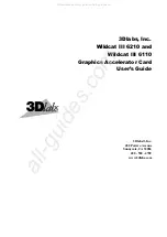
Owing to the limitation of number of HSMC connector I/O pins, SC connector and USB transceiver share some
I/O pins together, Please refer to
Figure 3.5
, those I/O pass through a Bus Switch chip first and then connect with
HSMC connector. Therefore users can only choose one function between SC connector and USB transceiver.
Users can refer to
Table3.1
and use JP2 to choose a function
In addition, from the
Figure 3.6
, there are several level shift chips between HSMC and SC. Theses level shift
chips convert the logic levels of the signals between the HSMC and Santa Cruz connectors according to the
configurations of the headers (JP3, JP4). With this feature, users can use different I/O standards between the
HSMC host board and SC interface daughter board.
Table 3.2
and
Table 3.3
list the configurations of the voltage
level of the HSPROTO_IO BUS and the PROTO_IO BUS, respectively.
BUS
Switches
(U1~U2)
Santa Cruz
Connectors
(J3~J5)
Level
Shifters
(U3~U8)
USB OTG
Transceiver
(U11)
HSPROTO_IO[14..0]
HSPROTO_IO[40..15]
SWPROTO_IO[14..0]
PROTO_IO[40..0]
HSPROTO_RESET
SWPROTO_RESET
16
USB_D[7..0]
USB_CS_n
USB_CLKOUT
USB_NXT
USB_STP
USB_DIR
USB_RESET_n
14
16
27
HSPROTO_CARDSEL
PROTO_CARDSEL
43
PROTO_RESET
HSMC Connector (J1)
JP1
DEV_SEL
Open : USB
Close : Santa Cruz
Figure 3.5. The I/O distribution of the HSMC, Santa Cruz, and USB transceiver interface.
Table 3.1
The configuration of the Enable function on bus switch chip
JP1 setting
Enable Function
Open
USB OTC Transceiver
Close
Santa Cruz conenctor