MLT2 User Manual
30
www.terasic.com
April 12, 2016
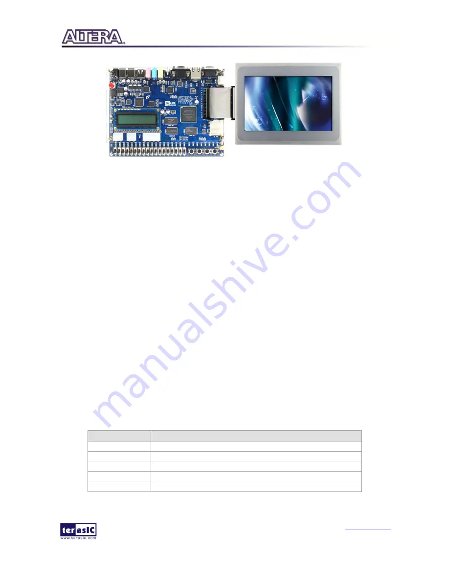
Figure 5-8 Hardware Setup with DE2-115
E
E
x
x
e
e
c
c
u
u
t
t
e
e
D
D
e
e
m
m
o
o
n
n
s
s
t
t
r
r
a
a
t
t
i
i
o
o
n
n
Please follow the procedures below to setup the demonstration:
1.
Make sure the DE2-115 is powered off.
2.
Mount the ITG adapter onto the 2x20 GPIO 0 expansion header of the DE2-115.
3.
Connect the DE2-115 USB-Blaster USB-B port to the PC USB Port with a USB Cable.
4.
Power on the DE2-115 FPGA Development Board.
5.
Make sure Quartus II 13.1 and NIOS II 13.1 are installed on your system.
6.
Copy the folder Demonstrations/Qsys/DE2_115_MTL2_PAINTER/demo_batch in the MTL
System CD onto your system and execute “test.bat”.
7.
Now, you should see the painter GUI on the LCD.
5.4
D
D
e
e
m
m
o
o
n
n
s
s
t
t
r
r
a
a
t
t
i
i
o
o
n
n
S
S
o
o
u
u
r
r
c
c
e
e
C
C
o
o
d
d
e
e
The source code locations of this demonstration for the various Terasic FPGA boards are shown in
Table 5-1.
Note: The project is built under Quartus II 13.1, and both Altera VIP license and Terasic
Multi-Touch IP license are required for rebuilding the project.
Table 5-1 Source Code Locations of Painter Demonstration
FPGA Board
Location
DE2
Demonstrations\Qsys\DE2_MTL2_PAINTER
DE2-115
Demonstrations\ Qsys \DE2_115_MTL2_PAINTER
DE1-SoC
Demonstrations\ Qsys \ DE1-SoC _MTL2_PAINTER
DE0-Nano
Demonstrations\ Qsys \ DE0-Nano _MTL2_PAINTER
DE0-CV
Demonstrations\ Qsys \DE0-CV _MTL2_PAINTER
Summary of Contents for MTL2
Page 1: ...p ...


