Section 4 (Con’t.)
7.
CUSTOM CALIBRATION NAMES.
Custom Calibrations (listed as Custom 0 - 9) can be renamed so that
the Main Display indicates your name for the calibration instead of
Custom 1, 2, etc. From the Main Display use the
↑
and
↓
keys until
SETUP
is selected. Press
ENTER.
Using the
↑
and
↓
keys select
Custom Names.
Press
ENTER.
Next, using the
↑
and
↓
arrows select
calibration number, or previous name you wish to rename. Press
ENTER.
Using the
↑
and
↓
keys select the number, letter or character
for the beginning of your new name. Press
ENTER.
Follow the same
procedure for each sequential letter or space of your new description.
Continue pressing
ENTER
until all spaces in the description have
entered values. Once your new name has been entered you will be
returned to the
SETUP
screen. To select your new calibration follow
the procedures outlined in Sec.3.6.
8.
MONITORING TENSION THROUGH THE ANALOG OUTPUT.
(Optional feature)
Output values are: 0 – 5 VDC or 4 – 20 mA.
Connect Analog Output Cable to receptacle located on the bottom side
of instrument. Connect output cable leads to the analog input of your
measurement or control device. The
RED
lead is V, the
WHITE
lead is mA, and the
BLACK
lead is ground. From the main
display use the
↑
and
↓
keys until you reach
SETUP.
Press
ENTER
.
Next using the
↑
and
↓
arrows select
ANALOG OUTPUT.
Press
ENTER.
Using the
↑
and
↓
arrows select from:
ANALOG TENSION
CURRENT
or
ANALOG TENSION VOLTAGE.
Once correct selection
is made press
ENTER.
9.
CALIBRATION OF ANALOG OUTPUT
.
(Optional feature)
From Main Display press the
↑
and
↓
keys until you reach
SETUP.
Press
ENTER.
Press the
↑
and
↓
keys until you reach
CALIBRATE
ANALOG.
Press
ENTER.
Using the
↑
and
↓
keys adjust display to
show the value at which the instrument reads maximum current or
voltage. Press
ENTER.
10.
SERIAL DATA COLLECTION (RS-232 option).
(Optional feature)
Instruments outfitted with the optional RS-232 feature (designated with
an –E in the part number) support serial communications as follows:
a. The baud rate is 9600 with no parity bit, 8 data bits and 1 stop bit
(9600 8N1).
b. Serial communications will work with most PCs with a cable up to
15 feet long.
Page 4 ACX-Series Operating Instructions
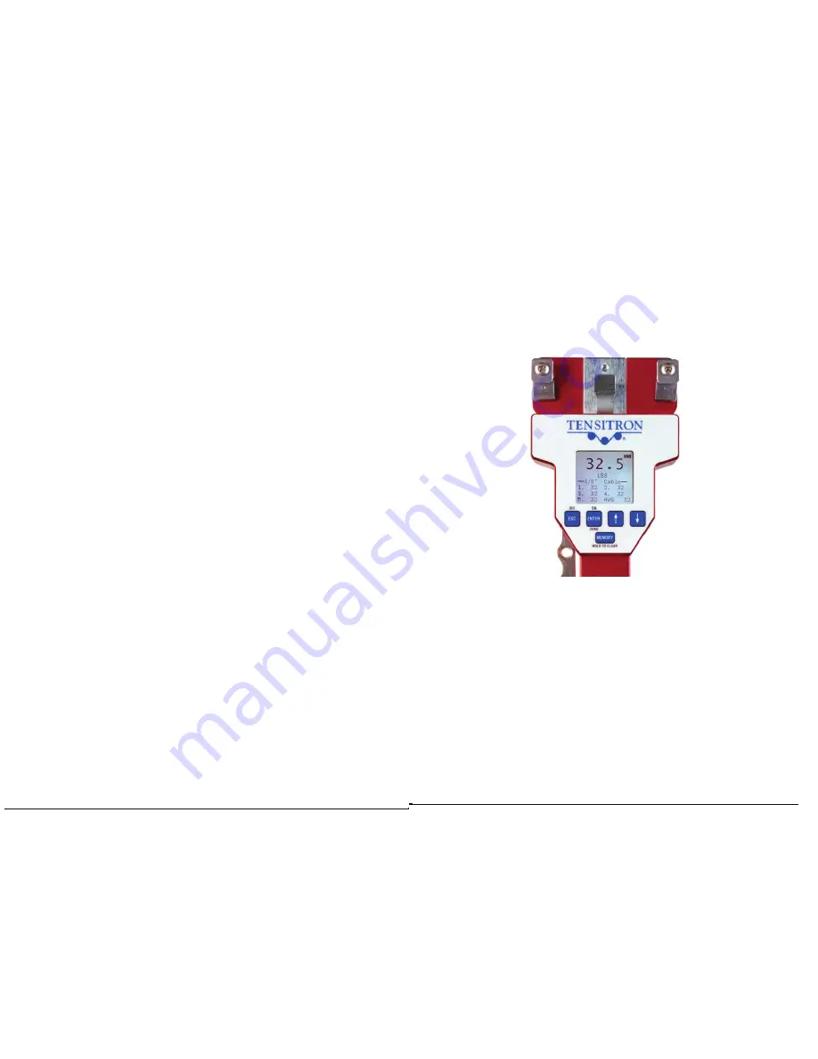
Fig 2, Confirming Cable Selection
* Confirm that the size cable you’re working with is the same size
selected in your ACX’s display. (In this example we’re checking
1/8” aircraft cable.)
Fig 2.
Before engaging the ACX instrument onto the cable, hold it in the
same attitude you’ll be taking the readings in and press the “Enter”
or “Zero” button. This will eliminate any small tare effect created
by gravity
.
ACX-Series Operating Instructions Page 13
NEVER SIMULATE TENSION LOADS ON THESE INSTRUMENTS
BY USING A CALIBRATION BAR!
Doing so could damage the
instrument to the point of failure.


