Page 3 of 7
KIT NO. 9006309--5680, 9006310--5700/5700XP
5680/5700/5700XP
ec-H2O
Kit
INSTALLATION INSTRUCTIONS --
Continued
9005074 Rev. 01 (05--09)
Tennant Company
Customer Service: (800) 553--8033 or (763) 513--2850
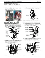
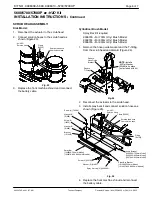
3. Connect the remaining
ec--H2O
harness wires to
the contactor terminals as shown (Figure 11). After
connecting harness, close the control console.
Orange 3B
Purple 47D
Brush
Contactor
Main
Contactor
Fig. 11
INSTALL THE
ec- H2O
SOLUTION SYSTEM:
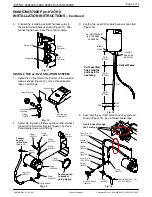
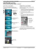
1. Install the in--line filter to the bottom of the solution
tank as shown (Figure 12). Use a thread sealer
tape on all fittings.
Remove plug
and discard
Fitting [1005218]
Solution tank
In--line Filter
[1005388]
Fitting
[79273]
Fig. 12
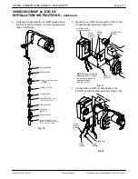
2. Assemble the pump fittings as shown and connect
the pump to the pump bracket (Figure 13). Use a
thread sealer tape on all fittings.
Fitting
[150418]
Fitting
[150709]
Fitting
[150006]
Pump
[1042495]
Fitting
[1005630]
Clamp [43844]
Fitting
[150515]
Clamp
[43555]
Fasten pump
to bracket
using clamp
Connect
hose to
in--line filter
(Figure 12)
Hose (2ft)
[376720]
Pump
bracket
Clamp
[43844]
Fig. 13
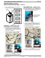
3. Cut the two
ec--H2O
module hoses as specified
(Figure 14).
ec--H2O
Module
14 in
(61cm)
20 in
(51cm)
2.25 in (5.7cm)
Outlet
Hose has
an Arrow
Intake
Hose
[p/n 1053250
or1048395]
Cut both hoses
20 in
(51cm)
Cut both hoses
Cut
Cut
Cut
Cut specified
hose lengths
and save for
next step
Fig. 14
4. Assemble the
ec--H2O
solution hose system as
shown (Figure 15). Use a thread sealer tape.
Hose (Fig. 14)
(20”/51cm)
Route hoses through
the 3 clamps
Clamp (7)
[603654]
Fitting
[150510]
Valve
[1044790]
Fitting
[150520]
Hose (Fig. 14)
(2.25”/5.7cm)
Pressure Switch
[1044415]
Fitting
[607306]
Fitting
[150713]
Hose [578227000 -- 3ft]
(cut to 27”/68.5cm)
Fig. 15


