background image

MAINTENANCE

830 MM332 (3--96)

72

ENGINE

COOLING SYSTEM

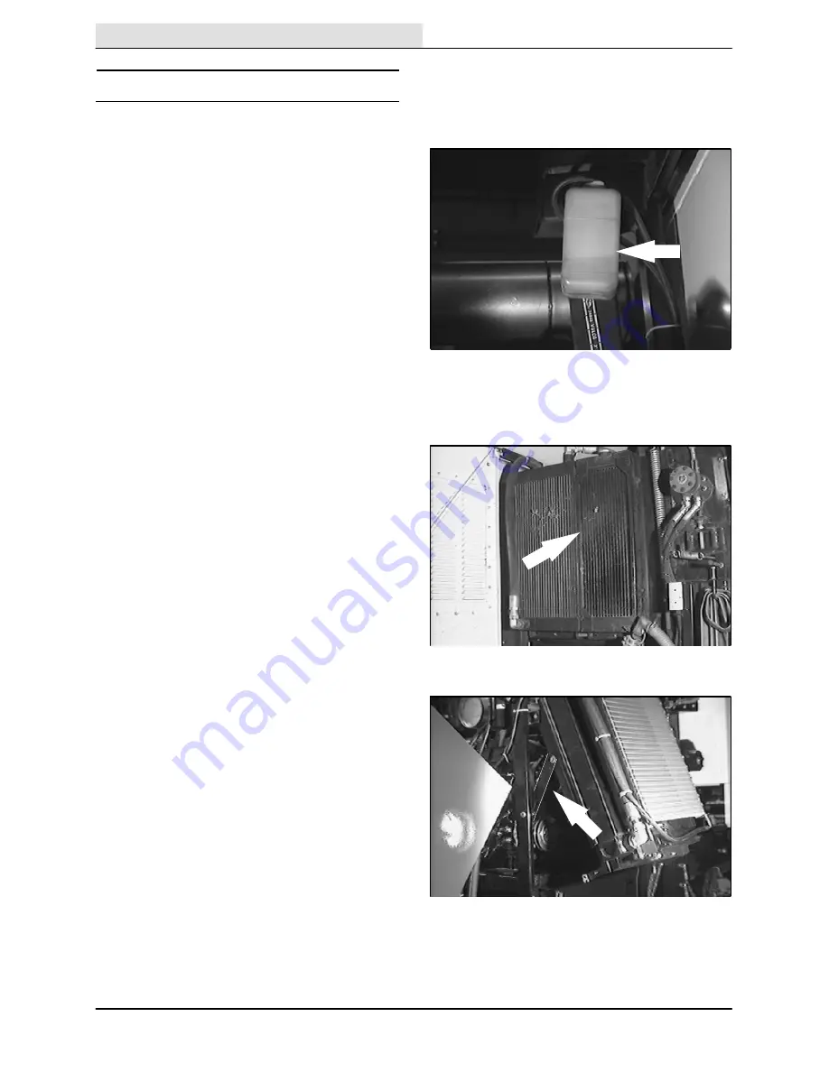
Check the radiator coolant level daily in the

overflow reservoir. Use clean water mixed with a

permanent-type, ethylene glycol antifreeze to a

--34

_

C (--30

_

F) rating. Add coolant to the

overflow reservoir.

FOR SAFETY: When Servicing Machine,

Avoid Contact With Hot Engine Coolant.

Check the radiator hoses and clamps every

200 hours of operation. Tighten the clamps if they

are loose. Replace the hoses and clamps if the

hoses are cracked, harden, or swollen.

Check the radiator core exterior and hydraulic

cooler fins for debris daily. The hydraulic cooler

blocker (if used) must be removed to clean the

hydraulic cooler fins. Blow or rinse all dust, which

may have collected on the radiator, in through the

grille and radiator fins, opposite the direction of

normal air flow. Be careful not to bend the cooling

fins when cleaning. Clean thoroughly to prevent

the fins becoming encrusted with dust. Clean the

radiator and cooler only after the radiator has

cooled to avoid cracking.

FOR SAFETY: When Servicing Machine,

Wear Eye And Ear Protection When

Using Pressurized Air Or Water.

Flush the radiator and the cooling system every

1600 hours of operation, using a dependable

cleaning compound.

The radiator and hydraulic cooler assembly pivots

forward for cleaning or for accessing the front of

the engine. To pivot forward, unscrew the bottom

two bolts, pull the assembly forward and engage

the locking latch.

Summary of Contents for 830

Page 1: ...830 MM332 Rev 08 Operator Manual MM332 ...
Page 2: ... This machine will provide excellent service However the best results will be obtained at minimum costs if D The machine is operated with reasonable care D The machine is maintained regularly per the maintenance instructions provided D The machine is maintained with TENNANT supplied or equivalent parts Manual Number MM332 Revision 08 Published 6 98 Copyright E 1993 1994 1995 1996 1997 1998 TENNANT...

Page 3: ...21 HOPPER TILT LIGHT 21 VACUUM WAND DOOR LIGHT OPTION 22 CONVEYOR UP AND MAIN BRUSH OFF LIGHT 22 CONVEYOR DOWN AND MAIN BRUSH ON LIGHT 22 WATER PUMP SWITCH OPTION 22 Page 4 WAY WARNING LIGHTS SWITCH 23 HAZARD LIGHTS SWITCH 23 REAR NIGHT SWEEPING LIGHT SWITCH OPTION 23 FRONT NIGHT SWEEPING LIGHT SWITCH OPTION 23 SIDE BRUSH SPOT LIGHT SWITCH 24 DIRECTIONAL LEVER 24 AIR CONDITIONER KNOB OPTION 24 REC...

Page 4: ...OR CHAIN 68 HYDRAULICS 69 HYDRAULIC FLUID RESERVOIR 69 HYDRAULIC FLUID 70 HYDRAULIC HOSES 71 PURGING AIR FROM THE HYDRAULIC CONVEYOR LIFT SYSTEM 71 Page ENGINE 72 COOLING SYSTEM 72 AIR FILTER INDICATOR 73 AIR INTAKE SCREEN 73 AIR FILTER 73 FUEL FILTER 74 FUEL LINES 74 PRIMING FUEL SYSTEM 75 TO PRIME FUEL SYSTEM 75 CAB FILTERS 76 WET DUST CONTROL FILTER OPTION 76 WINDSHIELD WIPER BLADES 77 WINDSHIE...

Page 5: ...Riders On Machine Always Follow Safety And Traffic Rules Report Machine Damage Or Faulty Operation Immediately 5 Before Leaving Or Servicing Machine Stop On Level Surface Set Parking Brake Turn Off Machine And Remove Key 6 When Servicing Machine Avoid Moving Parts Do Not Wear Loose Jackets Shirts Or Sleeves Block Machine Tires Before Jacking Machine Up Jack Machine Up At Designated Locations Only ...

Page 6: ... Engine Emits Toxic Gases Severe Respiratory Damage Or Asphyxiation Can Result Provide Adequate Ventilation Consult With Your Regulatory Agency For Exposure Limits Keep Engine Properly Tuned WARNING Lift Arm Pinch Point Stay Clear Of Hopper Lift Arms WARNING Moving Belt And Fan Blades Keep Away WARNING Do Not Store Hopper Support Bar On Cylinders CALIFORNIA PROPOSITION 65 WARNING Engine exhaust fr...

Page 7: ...RUSH Located On The Front Of The Machine HIGH DUMP LABEL Located On The Operator Dash EMISSIONS LABEL Located On The Operator Dash 09212 FOR SAFETY LABEL Located On The Operator Dash SIDE BRUSH LABEL Located Above The Side Brush es HOPPER SUPPORT BAR LABEL For Machines Below Serial Number 001710 Located On The Machine Frame LIFT ARMS LABEL Located On The Hopper Lift HOPPER SUPPORT PIN LABEL For Ma...

Page 8: ...CONVEYOR LABEL Located At The Top Of The Conveyor 09212 FLAMMABLE MATERIALS LABEL Wet Dust Control Option Located On The Water Tank HOPPER DOOR LABEL Located Below The Hopper Door HOPPER TILT CYLINDERS LABEL For Machines Below Serial Number 001710 Located On The Hopper Tilt Cylinders HOPPER SUPPORT PIN LABEL For Machines Serial Number 001710 And Above Located On The Upper Support Cylinder ...

Page 9: ...ed in the MAINTENANCE section of this manual Read this manual carefully before operating this machine FOR SAFETY Do Not Operate Machine Unless Operation Manual Is Read And Understood The model 830 has a GVWR of 9072 kg 20 000 lb or 4536 kg 10 000 lb per axle Operate only on surfaces capable of supporting this weight Check the machine for shipping damage Check to make sure machine is complete per s...

Page 10: ...y Check the tire pressure for all four tires See TIRES in the MAINTENANCE section After the first 50 hours of operation follow the recommended procedures stated in the MAINTENANCE CHART Keep your machine regularly maintained by following the maintenance information in this manual We recommend taking advantage of a regularly scheduled service contract from your TENNANT representative Order parts an...

Page 11: ... F G H I J K M N 09540 A Cab H Vacuum Wand B Diesel Engine I Hopper Lift C Conveyor J Main Brush D Hopper K Side Brush es E Dust Filters L Water Tank left side F Vacuum Fan M Fuel Tank G Hopper Door N Vario Sweeping Brusht Option or Auxiliary Side Brush Option ...

Page 12: ...ry Side Brush Vario Sweeping Bright Headlights Brusht Left Vario Sweeping Brusht Left Side Oil Pressure Vario Sweeping Brusht Right Side Charging System Auxiliary Side Brush Vario Sweeping Parking Brake Brusht Front Tilt Up Auxiliary Side Brush Vario Sweeping Solution Level Brusht Front Tilt Down Auxiliary Side Brush Vario Sweeping Hopper Overload Brusht Side Tilt Left Auxiliary Side Brush Vario S...

Page 13: ...in Brush Down and On Front Spot Light Filter Shaker Side Brush Spot Light Left Side Brush Forward Side Brush Down and On Reverse Water Valve Flow Rate Air Conditioner Vario Sweeping Brusht Rotation Counter clockwise Fan Auxiliary Side Brush Vario Sweeping Brusht Rotation Clockwise Heater Right Side Brush Debris Lift Forward Direction Side Brush Down and On Debris Lift Reverse Direction Fuse ...

Page 14: ... Front Angle Switch Option D Vario Sweeping Brusht Side Angle Switch Option E Fuel Level Gauge F Engine Water Temperature Gauge G Tachometer H Hourmeter I Indicating lights section consisting of Charging System Light Engine Oil Pressure Light Glow Plugs Light Signal Light Bright Headlights Light Parking Brake Light Water Tank Low Light J Hopper Overload Light High Dump Model K Hopper Door Light L ...

Page 15: ...ilter Shaker Lever FF Left Side Brush Lever Option GG Vario Sweeping Brusht Direction Lever Option or Auxiliary Side Brush Direction Lever Option HH Right Side Brush Lever II Left Side Brush Water Valve Knob Option JJ Vario Sweeping Brusht Left Water Valve Knob Option KK Vario Sweeping Brusht Right Water Valve Knob Option LL Right Side Brush Water Valve Knob Option MM Steering Wheel NN Parking Lig...

Page 16: ...h Right Move and hold the lever to the right into the position until the brush has moved to the desired location Left Move and hold the lever to the left into the position until the brush has moved to the desired location Up Move and hold the lever up into the position until the brush has moved to the desired location Down Move and hold the lever down into the position until the brush has moved to...

Page 17: ...and hold the switch in the position until the brush is tilted to the angle desired when operating the brush on the left side of the machine Tilt to the Right Press and hold the switch in the position until the brush is tilted to the angle desired when operating the brush on the right side of the machine VARIO SWEEPING BRUSHt DIRECTION LEVER OPTION The Vario Sweeping Brusht direction lever controls...

Page 18: ...ne is shut off water will continue to flow NOTE The water pump needs to be on for the water valves to operate VARIO SWEEPING BRUSHt RIGHT WATER VALVE KNOB OPTION The Vario Sweeping Brusht right water valve knob controls the amount of water spray to the sweeping brush when the it is on the right side of the machine Increase Water Spray Turn the water valve knob counter clockwise Decrease Water Spra...

Page 19: ...on until the brush has moved to the desired location Down Move and hold the lever down into the position until the brush has moved to the desired location AUXILIARY SIDE BRUSH FRONT ANGLE SWITCH OPTION The auxiliary side brush switch controls the front angle of the side brush Decrease Front Angle Press and hold the switch in the position Increase Front Angle Press and hold the switch in the positi...

Page 20: ...e coolant temperature If the engine coolant temperature rises above 120_ C 250_ F stop operating the machine locate the problem and have it corrected TACHOMETER The tachometer shows the engine RPM Move the throttle lever till the tachometer shows the desired engine RPM for the type of sweeping you are doing Refer to the chart in the SWEEPING section NOTE If the tachometer does not engage when firs...

Page 21: ...he charging system light stays on when first starting the machine rapidly increase the throttle until the light goes out Then adjust the throttle to the desired engine RPM ENGINE OIL PRESSURE LIGHT The engine oil pressure light comes on when the engine oil pressure falls below 35 kPa 5 psi Stop operating the machine Locate the problem and have it corrected GLOW PLUGS LIGHT The glow plugs light com...

Page 22: ... on BRIGHT HEADLIGHTS LIGHT The bright headlights light comes on when the bright headlights are on PARKING BRAKE LIGHT The parking brake light comes on when the parking brake is set WATER TANK LOW LIGHT OPTION The water tank low light comes on when the water tank level is low The water pump will shut off soon after this light comes on ...

Page 23: ...ted to low dump HOPPER DOOR LIGHT The hopper door light comes on when the hopper door is unlatched Make sure the hopper door is closed and latched and the hopper door light is off before sweeping with the machine HOPPER TILT LIGHT The hopper tilt light comes on when the hopper is tilted back Make sure the hopper is lowered into the sweeping position and the hopper tilt light is off before sweeping...

Page 24: ...e transporting the machine This green light may turn off while transporting If the red conveyor down and main brush on light comes on while transporting relift the conveyor CONVEYOR DOWN AND MAIN BRUSH ON LIGHT The red conveyor down and main brush on light comes on when the conveyor is lowered to the sweeping height and the main brush is rotating Make sure the conveyor down and main brush on light...

Page 25: ...ress the bottom of the hazard lights switch The light will go off REAR NIGHT SWEEPING LIGHT SWITCH OPTION The rear night sweeping light switch powers on and off the rear sweeping light On Press the top of the rear night sweeping light switch The light will come on Off Press the bottom of the rear night sweeping light switch The light will go off FRONT NIGHT SWEEPING LIGHT SWITCH OPTION The front n...

Page 26: ... unless the directional lever is in the neutral position Reverse Pull the lever down into the Reverse position AIR CONDITIONER KNOB OPTION The air conditioner knob controls the air conditioner temperature Increase The Cool Temperature Turn the air conditioner knob clockwise Decrease The Cool Temperature Turn air conditioner the knob counter clockwise NOTE The air conditioner will NOT work unless t...

Page 27: ...the heater temperature Increase Turn the heater knob clockwise Decrease Turn heater the knob counter clockwise DEBRIS LIFT DIRECTION SWITCH The debris lift direction switch controls the direction of the debris conveyor Forward Place the debris lift switch in the position This direction lifts debris into the hopper Reverse Place the debris lift switch in the position This direction reverses the con...

Page 28: ...logged debris lift FU 12 7 5 A Debris lift FU 13 5 A Brake lights FU 14 15 A Turn signals 4 way flashers FU 15 10 A Hazard lights FU 16 7 5 A Horn FU 17 10 A Radio option FU 18 25 A Operating lights FU 19 Spare FU 20 Spare FU 21 20 A Night sweeping lights HOPPER DOOR LEVER The hopper door lever latches and unlatches the hopper door When the hopper is tilted out the hopper door will swing open when...

Page 29: ...osition and rotation of the main brush and the position of the conveyor Lower and Start Pull and hold the main brush and conveyor lever in the position until the conveyor down and main brush on light comes on Raise and Stop Push and hold the main brush and conveyor lever in the position When the conveyor up and main brush off light comes on hold in this position for about 5 seconds before releasin...

Page 30: ...sition The throttle should be at 1800 RPM Up and Off Pull the right side brush lever into the position LEFT SIDE BRUSH WATER VALVE KNOB OPTION The left side brush water valve knob controls the amount of water spray to the left side brush Increase Water Spray Turn the left side brush water valve knob counter clockwise Decrease Water Spray Turn the left side brush water valve knob clockwise Stop Wat...

Page 31: ...it comes to a complete stop to close the water supply If this is NOT done when the machine is shut off water will continue to flow NOTE The water pump needs to be on for the water valves to operate STEERING WHEEL The steering wheel controls the machine s direction The machine is very responsive to the steering wheel movements Left Turn the steering wheel to the left Right Turn the steering wheel t...

Page 32: ...h lever down Bright Headlights Off Pull the switch lever up Flash Bright Headlights Pull the switch lever up then release Signals Push the switch lever forward for the right signal Pull the switch lever back for the left signal WINDSHIELD WIPER AND WASHER SWITCH The windshield wiper and washer switch controls the windshield wipers and windshield washer fluid spray Windshield Wipers Off Push the le...

Page 33: ...key all the way clockwise Release the key as soon as the engine starts Stop Turn the key counter clockwise PROPELLING PEDALS The propelling pedals control the propelling speed of the machine You change the speed of the machine with the pressure of your foot the harder you press the faster the machine travels The right pedal is used mainly for sweeping and uses the manual throttle The left pedal is...

Page 34: ...r controls the engine speed Fast Push the lever forward Idle Pull the lever backward LATCHES The cab doors side doors and main brush access doors are secured with latches Open the Cab Doors Pull out on the latch handle Open the Side Doors Pull out on the latch handle Open the Main Brush Access Doors For machines below serial number 001710 turn the door knob counter clockwise until the knob comes l...

Page 35: ... The seat front to rear position is adjusted by the seat position lever Adjust Push the lever to the left slide the seat backward or forward to the desired position and release the lever The ride stiffness is adjusted with the stiffness knob Adjust Turn the knob clockwise to increase the ride stiffness and counter clockwise to decrease the ride stiffness ...

Page 36: ...N For Machines Serial Number 001710 And Above The hopper support pin holds the hopper in the tilted position to allow work under the hopper DO NOT rely on the machine hydraulic system to keep the hopper raised WARNING Raised Hopper May Fall Engage Hopper Support Pin HOPPER SUPPORT PINS High Dump Model The hopper support pins holds the hopper in the raised position to allow work under the hopper DO...

Page 37: ...sh The main brush sweeps debris from the surface onto the conveyer which transfers the debris into hopper The vacuum system pulls dust and air through the hopper and the hopper dust filters The machine has a left side brush a Vario Sweeping Brusht and an auxiliary side brush option There is also a dust control water system When sweeping is finished clean the hopper dust filter and empty the hopper...

Page 38: ...OPERATION 830 MM332 9 95 36 Check the air filter intake screen at the top of the cab for obstructions Check the engine oil level Check fuel level Check the brakes and steering for proper operation ...

Page 39: ...830 MM332 12 93 Check fuel filter water trap for water Check the coolant level in the overflow reservoir Check the radiator core exterior and hydraulic cooler fins for debris Check the windshield washer fluid level ...

Page 40: ...to the idle position 3 Make sure the directional lever is in neutral NOTE Machine will not start unless the directional lever is in the neutral position 4 Turn the key counter clockwise The glow plugs light will come on When the glow plug light goes out usually for 5 to 30 seconds depending on the weather conditions the engine is ready to start NOTE The preheat is not necessary if the temperature ...

Page 41: ... if the charging system light stays on rapidly increase the throttle until the light goes out and the tachometer engages Then adjust the throttle to the desired engine RPM 7 Release the machine parking brake 8 Place the directional lever in the Forward position 9 Press on the left propelling pedal to transport the machine The more foot pressure the faster the machine will travel 10 Drive the machi...

Page 42: ...g the steering wheel too sharply when the machine is in motion The machine is very responsive to the movement of the steering wheel Avoid sudden turns except in emergencies Use the wet dust control option in dusty conditions For best results use the correct brush type for your sweeping application The following are recommendations for main and side brush applications Polypropylene and Wire Side Br...

Page 43: ...sweeping you are doing Refer to the following chart Debris Engine RPM Travel Speed Fine Dust 1500 RPM Normal Light Debris Leaves grass Shake filter often 2000 RPM Normal Wet Sweeping Vacuum fan on 2000 RPM Normal General Debris 1800 RPM Normal Heavy Debris 2000 RPM Slower than Normal Vacuum Wand Ear plugs mandatory 2500 RPM None NOTE Do NOT sweep with engine speed higher than 2000 RPM NOTE If the ...

Page 44: ... and start the main brush with the main brush and conveyor lever The conveyor down and main brush on light will come on 6 Lower the side brush with the right side brush lever 7 Lower the optional side brushes if equipped and needed 8 Start the vacuum fan with the vacuum fan and filter shaker lever ...

Page 45: ...ven after the machine is stopped To clear the jammed object stop sweeping reduce the engine speed and place the debris lift direction switch in the reverse position until the debris is removed Then place the switch back in the forward position and continue sweeping If there is too much heavy debris in the conveyor the alarm will sound constantly until the machine has stopped This means that the de...

Page 46: ...and main brush off light will come on 2 Stop the vacuum fan with the vacuum fan and filter shaker lever 3 Raise the side brush with the right side brush lever 4 Raise the optional side brushes if used 5 Shake the dust filters with the vacuum fan and filter shaker lever NOTE Shake the dust filter before tilting the hopper ...

Page 47: ...ight for the debris container NOTE Be aware that the minimum ceiling height needed to high dump the hopper is 4115 mm 13 5 ft WARNING High Dump Vertical Clearance Stay Clear Of Overhead Obstructions And Power Lines 3 Release the hopper lever in the middle Hold position 4 Place the directional lever in the Reverse position and slowly back the machine up to the debris site or container FOR SAFETY Wh...

Page 48: ...bris site or debris container FOR SAFETY When Using Machine Move Machine With Care When Hopper Is Raised 7 Push and hold the hopper lever in the position until the hopper has completely lowered and moved backed into the sweeping position The hopper tilt light will go off 8 Push the hopper door lever into the position WARNING Hopper Door Pinch Point Stay Clear Of Hopper Door ...

Page 49: ...ATION 47 830 MM332 8 94 STOP THE MACHINE 1 Stop sweeping 2 Take your foot off the propelling pedal Step on the brake pedal 3 Move the throttle lever back to the idle position 4 Set the machine parking brake ...

Page 50: ...d the cab fan Even with the machine off many of these accessories will continue to operate unless turned off POST OPERATION CHECKLIST Check the main brush adjustment See TO CHECK AND ADJUST MAIN BRUSH PATTERN in MAINTENANCE Check the brush skirts for damage and wear Check for wire or string tangled on the main and side brushes Check for fuel odor that indicates a fuel leak Check under the machine ...

Page 51: ...OPERATION 49 830 MM332 3 96 ENGAGING HOPPER SUPPORT BAR OR PIN 1 Set the machine parking brake 2 Start the engine 3 Tilt the hopper all the way back ...

Page 52: ...op of the cylinder rods with the tapered ends toward the hopper WARNING Raised Hopper May Fall Engage Hopper Support Bar For machine serial number 001710 and above remove the hopper support pin from the storage location on the right rear fender and place it into the hole of the hopper support cylinder WARNING Raised Hopper May Fall Engage Hopper Support Pin 5 Shut the engine off ...

Page 53: ...en it in the storage location on the right rear fender Do NOT store the hopper support bar on the hopper tilt cylinders WARNING Do Not Store Hopper Support Bar On Cylinders For machine serial number 001710 and above remove the hopper support pin and fasten it in the storage location on the right rear fender 2 Start the engine 3 Lower the hopper ...

Page 54: ...OPERATION 830 MM332 3 96 52 4 Shut the engine off ENGAGING HOPPER SUPPORT PINS High Dump Model 1 Set the machine parking brake 2 Start the engine ...

Page 55: ... 830 MM332 3 96 3 Raise the hopper all the way up 4 Install the red support pins in the designated hole on both sides of the machine WARNING Raised Hopper May Fall Engage 2 Hopper Support Pins 5 Shut the engine off ...

Page 56: ...0 MM332 3 96 54 DISENGAGING HOPPER SUPPORT PINS High Dump Model 1 Start the engine 2 Raise the hopper slightly to relieve pressure on the hopper support pins 3 Pull the support pins out of both sides of the machine ...

Page 57: ...hine slowly on inclines Use the brake pedal to control machine speed on descending inclines The maximum rated incline is 12_ with an empty hopper and 8_ with a full hopper Do not drive the machine on inclines with the hopper raised FOR SAFETY When Using Machine Move Machine With Care When Hopper Is Raised ...

Page 58: ...transport Make sure to take the hair cotter pin from the lock pin before the brush is operated WARNING Brush Linkage Pinch Points Stay Clear When Linkage Is Moving 1 Move the Vario Sweeping Brusht to the side of the machine needed for left and for right with the Vario Sweeping Brusht switch 2 Adjust the side angle of the brush with the Vario Sweeping Brusht side angle switch Use for the left side ...

Page 59: ...hine The brush arm moves along the front of the machine The brush movement front tilt angle and direction of rotation are adjusted for the right or left side The brush arm is latched to the front of the machine during transport Make sure the brush is unlatched before the brush is operated 1 Move the auxiliary side brush across the front of the machine to the desired location with the auxiliary sid...

Page 60: ...eaf pick up remove the skirt between the two side brushes DUST CONTROL SYSTEM The water spray dust control system is useful in dusty conditions to control the dust created by the side brushes The system consists of a water tank a water pump and spray nozzles for each of the side brushes 1 Fill the water tank The clear hose on the side of the tank indicates the water level in the tank WARNING Flamm...

Page 61: ...mes to a complete stop to close the water supply If this is NOT done when the machine is shut off water will continue to flow NOTE The water pump needs to be on for the water valves to operate 4 The water tank low light will come on when the water level is low in the tank The water pump will shut off soon after this light comes on NOTE Do not use the water system on wet roads Turn off the water pu...

Page 62: ... 1 Tilt the hopper back 2 Remove the vacuum wand door tool from under the hopper WARNING Lift Arm Pinch Point Stay Clear Of Hopper Lift Arms 3 Close the vacuum door with the vacuum wand door tool Place the tool back in its storage location under the hopper WARNING Conveyor Throws Debris Conveyor Pinch Point Stay Clear When In Operation 4 Lower the hopper ...

Page 63: ... the hopper door vacuum as required 8 Turn the water valve open if equipped when picking up mud or when wanting to clean the vacuum wand Turning the valve handle straight with the valve as shown opens the valve Turning the valve handle 90_ to the valve toward the operator closes the valve 9 Put the vacuum wand back on the hopper door 10 Reduce the throttle RPM 11 Shut off the vacuum fan 12 Tilt th...

Page 64: ...rush skirts or dust seals Hopper dust filter clogged Shake and or clean or replace dust filter Hopper not down completely Lower hopper completely Hopper rear door open Close and latch hopper rear door Vacuum wand door closed Open vacuum wand door Vacuum fan not on Turn vacuum fan on Vacuum fan failure Contact TENNANT service personnel Thermo Sentryt tripped Reset Thermo Sentryt Water tank empty Fi...

Page 65: ...r conveyor Free drive mechanism or con veyor of debris Conveyor in reverse Switch conveyor to forward direction Conveyor failure Contact TENNANT service personnel Conveyor skirts worn or damaged Replace conveyor skirts Hopper full Empty hopper Hopper not down completely Lower hopper completely Hopper rear door open Close and latch hopper rear door Vacuum wand door closed Open vacuum wand door Vacu...

Page 66: ... in overflow reservoir WG 1 3 Hydraulic fluid cooler Check and clean cooler fins 1 11 Hydraulic fluid reservoir Check fluid level HYDO 1 1 Brake fluid reservoir Check fluid level BF 1 10 Conveyor skirts and paddles Check for damage and wear All 9 Brush compartment skirts Check for damage and wear 3 5 Hopper door seal Check for damage and wear 1 9 Main brush Check for damage wear and adjustment 1 C...

Page 67: ...PL 2 14 Vario sweeping brush Lubricate rotation and guides SPL 2 12 Side brush Lubricate pivot SPL 2 3 Fuel filter Replace 1 7 Tires Check wear and rotate 4 Hydraulic hoses Check for wear and damage All 2 Battery Clean and tighten battery cable connections 1 Check electrolyte level DW 1 Wet dust control system Clean water filter 1 21 Windshield wiper blades Check for wear 2 400 Hours 15 Differenti...

Page 68: ...E 830 MM332 3 96 66 LUBRICATION A B C F G H I J A B C D D E E E E F K M N L P O 09541 A CONVEYOR BEARINGS There are four bearing grease fittings Lubricate daily with Lubriplate EMB grease TENNANT part no 01433 1 ...

Page 69: ...ase TENNANT part no 01433 1 every 200 hours of operation E WHEEL PIVOTS POINTS The wheel pivots points have eight grease fittings Lubricate with Lubriplate EMB grease TENNANT part no 01433 1 every 200 hours of operation F WHEEL LEAF SPRINGS The wheel leaf springs have twelve grease fittings Lubricate with Lubriplate EMB grease TENNANT part no 01433 1 every 200 hours of operation G SIDE BRUSH PIVOT...

Page 70: ...oil dipstick The engine oil capacity is 7 6 L 8 qt including the oil filter N DIFFERENTIAL Check the lubricant level in the differential every 400 hours of operation by removing the filler plug Change the differential lubricant every 1600 hours of operation Use SAE 90 weight gear lubricant O MAIN BRUSH SUPPORT RODS The main brush support rods have a total of eight grease fittings four on each side...

Page 71: ...rvoir Damage to the machine hydraulic system may result Drain and refill the hydraulic fluid reservoir with new hydraulic fluid every 800 hours of operation Mounted on top of the reservoir is a filler cap with a built in breather Replace the cap every 800 hours of operation Lubricate the filler cap gasket with a film of hydraulic fluid before putting the cap back on the reservoir The reservoir has...

Page 72: ...ler blocker is not used The hydraulic fluid is thermostatically controlled The higher temperature fluid has a higher viscosity and should not be used at the lower temperatures Damage to the hydraulic pumps may occur because of improper lubrication The lower temperature fluid is a thinner fluid for colder temperatures If a locally available hydraulic fluid is used make sure the specifications match...

Page 73: ...ed in the hydraulic fluid and cause the conveyor lift cylinder to slowly leak down from the raised position If a hydraulic component in the lift system has been replaced air will get into the hydraulic fluid This air must be purged from the system The conveyor lift cylinders have a built in feature called re phasing that allows the air trapped in the system to escape When the conveyor lift cylinde...

Page 74: ... be removed to clean the hydraulic cooler fins Blow or rinse all dust which may have collected on the radiator in through the grille and radiator fins opposite the direction of normal air flow Be careful not to bend the cooling fins when cleaning Clean thoroughly to prevent the fins becoming encrusted with dust Clean the radiator and cooler only after the radiator has cooled to avoid cracking FOR ...

Page 75: ...he air intake screen located on top of the cab for obstructions daily AIR FILTER The engine air filter housing has a dust cap and a dry cartridge type air filter element Check the dust cap every 100 hours of operation to make sure it is expelling dust Replace the dust cap if the rubber is worn The air filter element must be replaced whenever it is damaged or has been cleaned three times Inside the...

Page 76: ...rvicing Machine Keep Flames And Sparks Away From Fuel System Service Area Keep Area Well Ventilated Check the fuel filter water trap daily for water Drain any water visible in the bowl FUEL LINES Check the fuel lines every 50 hours of operation If the clamp band is loose apply oil to the screw of the band and securely tighten the band Made of rubber the fuel lines may become worn out whether the e...

Page 77: ... comes from the filter vent point 4 Loosen the return connection of the fuel injection pump 5 Operate the priming pump until fuel free from air comes from the injection pump vent point 6 Loosen all four of the high pressure fuel line connections at the injectors ATTENTION The engine may start running spontaneously if all four of the fuel line connections are not loosened 7 Operate the starter moto...

Page 78: ...of the cab Tap this filter clean The cab recirculation filter is located on the inside front of the cab in front of the passenger seat Clean this filter with soap and water WET DUST CONTROL FILTER OPTION The wet dust control filter is located under the cab between the front wheels Clean the water filter every 200 hours of operation by removing and flushing with clean water 09218 ...

Page 79: ...ld washer fluid level daily Fill with automotive type windshield washer fluid BATTERY The battery is located under the passenger seat After the first 50 hours of operation and every 200 hours after that clean and tighten the battery connections Check the electrolyte level every 200 hours of operation Only add distilled water FOR SAFETY When Servicing Machine Avoid Contact With Battery Acid ...

Page 80: ...TIONER BELT The air conditioner belt is driven by the engine crankshaft pulley and drives the compressor Proper belt tension is 4 mm 0 19 in from a firm force of a finger applied at the mid point of the longest span Check and adjust the belt tension after the first 10 hours of operation and then every 100 hours after that WARNING Moving Belt And Fan Blades Keep Away STATIC DRAG CHAIN A static drag...

Page 81: ...fore Leaving Or Servicing Machine Stop On Level Surface Set Parking Brake Turn Off Machine And Remove Key 2 Remove the top hopper cover 3 Remove the nuts holding the filter shaker frame in the hopper 4 Pull the filter shaker frame and filter out of the hopper 5 Drill out the rivets holding the filter to the shaker frame 6 Put the new separators into the new filter bag pockets 7 Take the rods out o...

Page 82: ...low The Thermo Sentryt is located at the rear of the hopper Remove the access panel above the hopper door Reset the Thermo Sentryt by pushing in its reset button CONVEYOR The conveyor transports debris picked up by the main brush to the hopper by means of a paddle system Check tension clean and lubricate the conveyor chain tensions daily The conveyor chain is tensioned automatically by the springs...

Page 83: ...n brush pattern daily The pattern should be 100 to 125 mm 4 to 5 in wide Adjust the main brush pattern with the main brush down pressure nut located under the hopper Replace the main brush when the remaining bristles measure 50 mm 2 in in length TO REPLACE MAIN BRUSH 1 Park the machine on level ground and set the machine parking brake 2 Lower the main brush 3 Stop the engine FOR SAFETY Before Leav...

Page 84: ...TENANCE 830 MM332 3 96 82 5 Remove the hardware holding the skid plates to the brush idler plate 6 Remove the hardware holding the links to the brush idler plate 7 Remove the brush chains and the skid chain ...

Page 85: ...otate the brush until it engages the drive plug and push it all the way onto the plug 13 Slide the main brush idler plate plug onto the main brush 14 Mount the idler plate onto the machine with the hardware removed earlier 15 Mount the brush chains and the skid chain 16 Mount the links to the idler plate with the hardware removed earlier 17 Mount the skid plates to the idler plate with the hardwar...

Page 86: ...e in one place for 2 minutes 3 Raise the main brush 4 Drive the machine off the test area 5 Observe the width of the brush pattern The proper brush pattern width is 100 to 125 mm 4 to 5 in 6 To increase the width of the main brush pattern turn the main brush down pressure nut counter clockwise To decrease the width of the main brush pattern turn the main brush down pressure nut clockwise ...

Page 87: ... remaining bristles measure 75 mm 3 in in length You may change the side brush sooner if you are sweeping light litter or wear the bristles shorter if you are sweeping heavy debris TO REPLACE SIDE BRUSH 1 Raise the side brush 2 Stop the engine and set the machine parking brake FOR SAFETY Before Leaving Or Servicing Machine Stop On Level Surface Set Parking Brake Turn Off Machine And Remove Key 3 R...

Page 88: ...the rear of the brush compartment The skirt should clear the ground by 3 mm 0 125 in Check the skirt for wear or damage daily NOTE Tire pressure and a full hopper will affect skirt clearances CONVEYOR SKIRTS The conveyor has a lip skirt located at the bottom rear of the conveyor and two side skirts The skirts should touch the ground when the conveyor is lowered into the sweeping position Check the...

Page 89: ...peration CONVEYOR SEALS The conveyor seals are located on the machine frame where the conveyor makes contact with the frame Check the seals for wear or damage every 100 hours of operation HOPPER SEALS The hopper seals are located on the hopper door the hopper filter cover the dust filter and the front opening of the hopper Check the seals for wear or damage every 100 hours of operation ...

Page 90: ...eck the rubber flaps every 100 hours of operation for damage or wear BRAKES AND TIRES SERVICE BRAKES The hydraulic service brakes are located on all four wheels The brake fluid reservoir is located in the cab under the dashboard Check the brake fluid level every daily The service brakes adjust automatically when the brakes are activated in reverse Periodically brake several times while driving in ...

Page 91: ...ront axle is equipped with a hydraulic valve for aligning the wheels This should be done after every 50 hours of operation or when the machine is not tracking properly To align the wheels start the machine and turn the steering wheel fully to the left Move the machine slightly forward and backward to get the full left hand turn Apply the parking brake Find the red valve handle and place it on the ...

Page 92: ...with a 13 mm wrench Turn out the set screws till they top out with a 4 mm allen wrench Tighten the nuts ATTENTION Do not push or tow the machine without using the towing valve or the machine hydraulic system may be damaged MACHINE TIE DOWNS The machine must be tied down on the main frame The front tie down locations are on the inside channels of the main frame Always set the machine parking brake ...

Page 93: ...jack with full hopper Always stop the machine on a flat level surface and block the tires before jacking up the machine The front jacking locations are the front axle The rear jacking locations are the rear axle FOR SAFETY When Servicing Machine Block Machine Tires Before Jacking Machine Up FOR SAFETY When Servicing Machine Jack Machine Up At Designated Locations Only Block Machine Up With Jack St...

Page 94: ...the water valve knobs on the dash panel to drain the lines 2 Drain the water tank with the drain valve located under the tank 3 Lay the vacuum wand option if machine is equipped on the ground and open the water valve on the wand Leave the valve open 4 Drain the water lines and pump by opening the drain valve at the water pump under the cab 5 Remove the water filter cap located next to the water pu...

Page 95: ...rush 3000 mm 118 in Main brush pattern width 100 to 125 mm 4 to 5 in Hopper weight capacity Low dump model 3496 kg 7700 lb Hopper weight capacity High dump model 2270 kg 5000 lb Hopper volume capacity 2600 L 3 4 yd3 Dust filter area 20 m2 211 sq ft Wet dust control water tank option 348L 92 gal GVWR 9072 kg 20 000 lb Axle rating front and rear 5000 kg 11 000 lb Ceiling height minimum dumping clear...

Page 96: ... 10W30 SAE CD SE rated engine oil Air conditioner Refrigerant R134a total system capacity 1 4 kg 3 lb STEERING Type Power source Emergency steering Front and rear wheels hydraulic cylinder steering rod and rotary valve controlled Hydraulic accessory pump Manual HYDRAULIC SYSTEM System Capacity Fluid Type Hydraulic reservoir 68 2 L 18 gal TENNANT part no 65870 Mobil no DTE13M above 0_ C 32_F Hydrau...

Page 97: ...mm 100 in 2055 mm 81 in 1905 mm 75 in Retracted 1780 mm 70 in Extended 3025 mm 119 in To Step 1765 mm 69 5 in 2920 mm 115 in 4290 mm 169 in 5450 mm 215 in Vac Wand To Aux Brush 5155 mm 203 in SIDE VIEW BOTTOM VIEW 1510 mm 59 5 in 10954 MACHINE DIMENSIONS ...

Page 98: ...s 78 Conveyor 80 Static drag 78 Charging system light 19 Controls 12 14 4 way warning lights switch 23 Air conditioner knob 24 Auxiliary side brush direction lever 17 Auxiliary side brush front angle switch 17 Auxiliary side brush lever 17 Brake pedal 31 Bright headlights light 20 Charging system light 19 Conveyor and main brush off light 22 Conveyor down and main brush on light 22 Debris lift dir...

Page 99: ...rection lift switch 25 43 Debris hopper 79 81 Debris lift direction switch 25 43 Differential Lubrication 68 Dimensions 93 Dimensions Machine 95 Directional lever 24 Disengaging hopper support bar or pin 51 52 Disengaging hopper support pins 54 56 Doors Brush Latch 32 Skirts 86 Cab Latch 32 Seals 87 Side Latch 32 Dust Control Wet Left side water valve 28 Right side water valve 29 Dust control Wet ...

Page 100: ...r pin 51 52 Disengaging hopper support pins 54 56 Door lever 26 Door light 21 Dust filter 79 Engaging hopper support bar or pin 49 51 Engaging hopper support pins 52 54 Filter cleaning 79 Lift 27 Overload light 21 Seals 87 Support bar 34 Support pin 34 Support pins 34 Thermo Sentry 80 Tilt light 21 Hopper door Operate 26 Hopper door lever 26 Hopper lever 27 Hopper overload light 21 Hopper support ...

Page 101: ...3 Glow plugs 19 Hazard lights switch 23 Headlights 30 Hopper door 21 Hopper overload 21 Hopper tilt 21 Parking 30 Parking brake light 20 Rear night sweeping light switch 23 Side brush spot light switch 24 Signal 20 Signals 30 Vacuum wand door 22 Water tank low 20 Lock pin Vairo sweeping brush 14 Lubrication 66 Auxiliary side brush 67 Conveyor bearings 66 Conveyor chains 68 CV joints 67 Differentia...

Page 102: ...io sweeping brush left water valve knob 16 Vario sweeping brush lever 14 Vario sweeping brush right water valve knob 16 Vario sweeping brush side angle switch 15 Vario sweeping brush switch 14 Water pump switch 22 Water tank low light 20 Wet dust control Filter 76 Wet dust control system Operation 58 60 P Parking brake 32 88 Light 20 Lubrication 67 Parking brake light 20 Parking lights headlights ...

Page 103: ...system 94 Machine capacities 93 Machine dimensions 93 Machine performance 93 Power type 94 Steering 94 Tires 94 Starting the machine 38 40 Static drag chain 78 Steering 36 Lubrication Cylinder 67 Specifications 94 Steering wheel 29 Stop sweeping 44 Stop the machine 47 49 Storing machine 92 Freeze protection 92 Sweeping 41 44 Sweeping and brush information 40 41 Switches 4 way warning lights 23 Aux...

Page 104: ...8 Right water valve knob 16 Side angle switch 15 Switch 14 W Water pump switch 22 Water tank low light 20 Weight limit 7 40 93 Wet dust control Operation 58 60 Wheel alignment 89 Wheel leaf spring Lubrication 67 Wheel nuts 89 Torque 89 Wheel pivots Lubrication points 67 Wheels Alignment 89 CV joints Lubrication 67 Leaf springs Lubrication 67 Nuts 89 Pivots points Lubrication 67 Windshield washer 7...

Reviews: