background image

OPERATION

10

Tennant 1100  (07–02)

6.

Remove and rinse solution tank screen 
(Figure 16).

FIG. 16

7.

Inspect power cord and cord grip for damage,
replace if damaged. Coil cord neatly after each
use.

8.

Clean machine with a nonabrasive, nonsolvent
cleaner (Figure 17).

FIG. 17

9.

Inspect vacuum hose for holes and loose cuffs.

MONTHLY MAINTENANCE
(Every 80 Hours of Operation)

1.

Flush pump system with an acetic acid solution to
dissolve normal alkaline chemical buildup.

FOR SAFETY: When using machine, follow mixing
and handling instructions on chemical containers.

a.

Premix .5L (16 oz) of an acetic acid solution
with 7.5L (2 gal) of hot water 60

_


C (140

_

F )

and pour into solution tank.

b.

Connect accessory tool to machine.

c.

Turn on the main power switch.

d.

With tool over a bucket, squeeze accessory
tool trigger for one minute.

e.

Shut off machine and allow remaining solution
to break down alkaline buildup overnight.

f.

Next day, spray out remaining solution and
flush system with 11L (3 gal) of clean water.

2.

Lubricate wheels and casters with a water
resistant oil.

3.

Inspect machine for water leaks.

4.

Inspect machine for loose screws.

QUARTERLY MAINTENANCE
(Every 250 of Hours of Operation)

Check vacuum motor for carbon brush wear. Replace
brushes when worn to a length of 10mm (0.38 in) or
less. Contact your Authorized Service Center for
carbon brush inspection.

SERVICING MACHINE

To access internal components for repair, open
machine as described below.

WARNING: Unplug Power Cord Before

Servicing Machine.

FOR SAFETY: When servicing machine, use
manufacturer supplied or approved replacement
parts.

1.

Remove two hex–head bolts at front of machine,
using a 9/16” wrench.

ATTENTION: Make sure tanks are empty before
opening.

2.

Carefully hinge tank backwards away from chassis
(Figure 18).

FIG. 18

3.

When closing machine, keep fingers clear and be
careful not to pinch or kink internal hoses or
wiring. Replace the lift handle and tighten the
hex-head bolts securely.

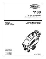
Summary of Contents for 1100

Page 1: ...ator and Parts Manual Manual del Operador y Piezas Portable Carpet Extractor Extractor Portátil de Alfombras CUSTOMER SERVICE 1 800 982 7658 1 616 786 2330 FAX 1 800 678 4240 1 616 786 2345 TENNANT COMPANY Commercial Products 12875 RANSOM STREET HOLLAND MI 49424 U S A ...

Page 2: ...ned with manufacturer supplied or equivalent parts MACHINE DATA Please fill out at time of installation for future reference Model No Install Date Serial No E2002 Tennant Company Printed in U S A TABLE OF CONTENTS SAFETY PRECAUTIONS 3 GROUNDING INSTRUCTIONS 4 SAFETY LABEL 4 MACHINE COMPONENTS 5 UNPACKING THE MACHINE 6 MACHINE SETUP 6 MACHINE OPERATION 7 PRE OPERATION 7 OPERATING FLOOR TOOL 7 CLEAN...

Page 3: ...s Do Not Expose to Rain Store Indoors The following information signals potentially dangerous conditions to the operator or equipment FOR SAFETY 1 Do not operate machine Unless trained and authorized Unless operator manual is read and understood In flammable or explosive areas Unless cord is properly grounded With damaged cord or plug If not in proper operating condition In outdoor areas In standi...

Page 4: ...ne is equipped with a cord having an equipment grounding conductor and grounding plug The plug must be plugged into an appropriate outlet that is properly installed in accordance with all local codes and ordinances Do not remove ground pin if missing replace plug before use Grounded 3 Hole Outlet Ground Pin SAFETY LABEL The safety label appears on the machine in the location indicated Replace labe...

Page 5: ... 5 254mm 10 in Stair Climbing Wheels 6 Bottle Holder 7 Main Power ON OFF Switch 8 Power Supply Cord Pigtail 9 Recovery Tank Drain Hose 10 Accessory Tool Solution Hose Hookup 11 Accessory Tool Vacuum Hose Hookup 12 4 6m 15 ft Vacuum Hose 13 4 6m 15 ft Solution Hose 14 330mm 13 in Floor Tool optional 15 7 6m 25 ft Power Supply Cord 16 1 4m 4 1 2 ft Clean Out Hose ...

Page 6: ...ING Do Not Use Flammable Liquids Or Operate Machine In Or Near Flammable Liquids Vapors Or Combustible Dusts 2 Add a recommended cleaning solution to the proper dilution ratio FOR SAFETY When using machine follow mixing and handling instructions on chemical containers ATTENTION If using powdered cleaning chemicals mix chemical with water prior to adding to the tank NOTE If desired water alone achi...

Page 7: ... Place the floor tool so the stainless steel shoes are parallel to the floor Squeeze the trigger and apply a downward pressure on the floor tool head and slowly pull the tool backwards Release trigger 150mm 6 in from end of stroke Figure 7 3 Push the floor tool forward over the same path with trigger released when returning to the next stroke Continue this pull and push method with a 50mm 2 in ove...

Page 8: ...cleaning strokes to avoid streaking Figure 8 FIG 8 WARNING Do Not Pick Up Flammable Materials Or Reactive Metals 5 While operating check for excessive foam buildup in recovery tank Use a recommended foam control solution to prevent vacuum motor damage ATTENTION Excessive foam buildup will not activate the float shut off screen Vacuum motor damage may result 6 When the accessory tool stops spraying...

Page 9: ...nk thoroughly Figure 11 FIG 11 2 Remove and clean the float shut off screen located in the recovery tank Figure 12 FIG 12 3 Vacuum out the leftover solution from the solution tank Figure 13 FIG 13 4 Inspect the accessory tool spray pattern for plugging If plugged remove the spray tips and screens and soak them in acetic acid solution for up to six hours Do not use pointed objects to unplug tips da...

Page 10: ...wn alkaline buildup overnight f Next day spray out remaining solution and flush system with 11L 3 gal of clean water 2 Lubricate wheels and casters with a water resistant oil 3 Inspect machine for water leaks 4 Inspect machine for loose screws QUARTERLY MAINTENANCE Every 250 of Hours of Operation Check vacuum motor for carbon brush wear Replace brushes when worn to a length of 10mm 0 38 in or less...

Page 11: ...vice Center Loose or broken wiring Contact Service Center Vacuum motor does not operate Vacuum motor thermal overload tripped Check air flow for obstruction wait 20 minutes for motor to cool Loose or broken wiring Contact Service Center Faulty switch Contact Service Center Defective vacuum motor Contact Service Center Worn carbon brushes Replace brushes or call for service Poor pick up Float shut ...

Page 12: ... SOLUTION TANK CAPACITY 38L 10 gal RECOVERY TANK CAPACITY 55L 14 5 gal SOLUTION PUMP 120V 6 9bar 100psi 1A VACUUM MOTOR 120V 1 8 hp 13A 1560W 3 stage SEALED WATER LIFT 3 5m 136 in TOTAL POWER CONSUMPTION 120V 14 0A 1680W DECIBEL RATING AT OPERATOR S EAR INDOORS ON CARPET 78dB A MACHINE DIMENSIONS 864mm 34 in 1016mm 40 in 406mm 16 in ...

Page 13: ... PARA LA CONEXIÓN A LA TOMA DE TIERRA 15 ADHESIVOS DE SEGURIDAD 15 COMPONENTES DE LA MÁQUINA 16 DESEMPAQUE DE LA MAQUINA 17 INSTALACIÓN DE LA MÁQUINA 17 FUNCIONAMIENTO DE LA MÁQUINA 18 ANTES DE LA PUESTA EN MARCHA 18 OPERACION DE LA HERRAMIENTA DE PISO 18 LIMPIEZA DE TAPIZADOS 19 VACIADO DE LOS DEPÓSITOS 19 VACIADO DEL DEPÓSITO DE RECUPERACIÓN 19 DRENAJE DE LA SOLUCION DE LIMPIEZA RESTANTE 20 MANT...

Page 14: ...lvo que haya leído y comprendido el manual del operario En lugares con material inflamable o explosivo Si la toma de tierra del cable eléctrico no funciona correctamente Con el cable eléctrico o enchufe en malas condiciones Si la máquina no funciona correctamente Al aire libre Cuando haya agua en el suelo Con el uso de cordones de extensión adicionales Use sólo el cordón de extensión del fabricant...

Page 15: ...tor de conexión a tierra del equipo y un enchufe de conexión a tierra El enchufe debe enchufarse en un tomacorrientes apropiado que esté bien instalado de acuerdo con todos los códigos y ordenanzas locales No extraiga la clavija de conexión a tierra en caso de faltar vuelva a colocar el enchufe antes de usar ENCHUFE CONEC TADO A TIERRA 3 ORIFICIOS CLAVIJA DE CONEXION A TIERRA ADHESIVOS DE SEGURIDA...

Page 16: ... 7 Conmutador ON OFF de electricidad principal 8 Cable flexible de alimentación eléctrica 9 Manguera de drenaje del tanque de recuperación 10 Gancho para la herramienta accesoria de la manguera de solución 11 Gancho para la herramienta accesoria de la manguera de vacío 12 Manguera de vacío de 4 6m 15 pies 13 Manguera de solución de 4 6m 15 pies 14 Herramienta para piso de 330mm 13 pul opcional 15 ...

Page 17: ... ADVERTENCIA No utilice líquidos inflamables o haga funcionar la máquina cerca de líquidos o vapores o polvos inflamables 2 Agregue una solución recomendada de limpieza a la relación apropiada de dilución PARA SU SEGURIDAD Siga las instrucciones de mezcla y manipulación indicadas en los envases de los productos químicos cuando utilice la máquina ATENCIÓN Si usa el polvo de limpieza mezcla el polvo...

Page 18: ...a herramienta de piso de manera que las zapatas de acero inoxidable estén paralelos al piso Oprima el gatillo y aplique una presión descendente sobre el cabezal de la herramienta de piso y lentamente tire de la herramienta hacia atrás Suelte el gatillo a 150mm 6 pul desde el extremo de la carrera Figura 7 3 Empuje la herramienta de piso hacia adelante sobre el mismo recorrido con el gatillo suelto...

Page 19: ...ado Repita la carrera sin rociado para secar la tela tanto como sea posible Superponga las carreras de limpieza para evitar estrías Figura 8 FIG 8 ADVERTENCIA No recoja materiales inflamables ni metales reactivos 5 Controle si existe formación excesiva de espuma en el depósito de recuperación Utilice una disolución recomendada para controlar la formación de espuma y evitar averías del motor ATENCI...

Page 20: ...nimiento diarias semanales o mensuales de la máquina PARA SU SEGURIDAD Al revisar la máquina desconecte el cable eléctrico del enchufe de la pared MANTENIMIENTO DIARIO Cada 4 horas de utilización 1 Vacíe y aclare bien el depósito de recuperación Figura 11 FIG 11 2 Extraiga y limpie el filtro del flotador cierre situado en el depósito de recuperación Figura 12 FIG 12 3 Sumerja la manguera de limpie...

Page 21: ...A SU SEGURIDAD Siga las instrucciones de mezcla y manipulación indicadas en los envases de los productos químicos cuando utilice la máquina a Mezcle 16 oz 5 litros de solución de ácido acético con 2 gal 7 5 litros de agua caliente temperatura máxima 140 F 60 C y viértala en el depósito de la disolución b Conecte la herramienta accesoria a la máquina c Encienda el conmutador de la electricidad prin...

Page 22: ...tenga los dedos alejados y sea precavido en no presionar o doblar las mangueras o el cableado internos Vuelva a colocar el mango de elevación y ajuste bien las tuercas de cabeza hexagonal ALMACENAMIENTO DE LA MÁQUINA 1 Antes de guardar la máquina asegúrese de aclarar y vaciar todo el agua de los depósitos de la máquina 2 Guarde la máquina en posición vertical en un sitio seco con el cepillo levant...

Page 23: ...rvicio técnico Recogida Es activado la mampara de flotar Tanque de recobro desaguadero insuficiente Tapón de la manguera de vaciado mal cerrado Cierre bien el tapón de la manguera de vaciado Filtro del flotador de cierre bloqueado Retire la tapa de recuperación y limpie el filtro del flotador de cierre Fuga de aire alrededor de la tapa de recuperación Colocar de nuevo la tapa de recuperación o sus...

Page 24: ...IDAD DEL DEPÓSITO DE LA DISOLUCIÓN 38L 10 gal CAPACIDAD DEL DEPÓSITO DE RECUPERACIÓN 55L 14 5 gal BOMBA DE LA DISOLUCIÓN 120V 6 9bar 100psi 1A MOTOR DE ASPIRACIÓN 120V 1 8 hp 13A 1560W 3 stage ELEVACIÓN SELLADA DE AGUA 3 5m 136 in POTENCIA TOTAL 120V 14 0A 1680W DECIBELIOS A LA ALTURA DEL OPERARIO EN RECINTO CERRADO CON SUELO ENMOQUETADO 78dB A ...

Page 25: ...OPERACIÓN 25 Tennant 1100 07 02 DIMENSIONES DE LA MÁQUINA 864mm 34 in 1016mm 40 in 406mm 16 in ...

Page 26: ...RAMS DIAGRAMAS ELECTRICAS Tennant 1100 07 02 26 120V WIRING DIAGRAM DIAGRAMA DE CABLEADO MOTOR PUMP MOTOR VACUUM GREEN BLACK WHITE 2 1 14 4 CORD WHITE GREEN 2 1 WHITE BLACK 1 2 3 BLACK MASTER SWITCH RED GREEN PLUG AC ...

Page 27: ...ELECTRICAL DIAGRAMS DIAGRAMAS ELECTRICAS 27 Tennant 1100 07 02 120V LADDER DIAGRAM DIAGRAMA DE CABLEADO MOTOR PUMP 1 2 3 MOTOR VAC SWITCH MASTER J1 120V PLUG 1 2 1 2 PART LOCATED IN CHASSIS ...

Page 28: ...0 07 02 28 RECOVERY TANK GROUP CONJ DEPOSITO RECUPERAR 1 3 7 2 4 5 6 4 5 6 8 9 10 60 11 12 13 14 15 16 19 20 17 18 21 27 33 32 34 35 22 23 24 25 24 26 37 38 39 40 41 42 43 44 45 46 47 48 52 53 54 55 56 57 59 29 31 30 28 49 36 50 51 52 58 56 ...

Page 29: ...N HOSE 1 Y 29 230882 DSTRAP RUBBER 1 Y 30 140056 WASHER FENDER 1 Y 31 140955 PLUG DRAIN HOSE 1 ASSEMBL Y C O N J U N T O Y INCLUDED I N A S S E M B L Y I N C L U I D O E N E L C O N J U N T O D RECOMMENDED S T O C K I T E M S A R T I C U L O S R E C O M E N D A D O S P ARA M A N T E N E R E N E X I S T E N C I A REF PART DESCRIPTION QTY 32 140921 SLEEVE DRAIN HOSE 1 33 140072 CLAMP HOSE 1 9 16 EAR...

Page 30: ...ZAS Tennant 1100 07 02 30 CHASSIS GROUP CONJUNTO TELAIO 1 2 3 4 3 8 7 13 3 9 12 13 3 4 10 11 10 9 14 15 16 17 18 19 20 25 26 27 28 28 27 26 29 30 31 36 35 37 38 10 24 5 6 30 32 22 34 33 36 44 45 42 42 41 40 39 43 41 21 23 43 ...

Page 31: ... 4X48 1 22 130181 GRIP CORD STRAIN RELIEF 1 2NPT 1 ASSEMBL Y C O N J U N T O Y INCLUDED I N A S S E M B L Y I N C L U I D O E N E L C O N J U N T O D RECOMMENDED S T O C K I T E M S A R T I C U L O S R E C O M E N D A D O S P ARA M A N T E N E R E N E X I S T E N C I A REF PART DESCRIPTION QTY 23 140504 NUT CONDUIT 1 2NPT LOCK 1 24 607723 FRAME CHASSIS 1100 TEAL 1 25 230739 AXLE WHEEL 1 2DX 13 1 8...

Page 32: ...PARTS LIST LISTA DE PIEZAS Tennant 1100 07 02 32 CONTROL CONSOLE GROUP CONJUNTO CONSOLA DE CONTROLES 1 2 3 4 5 6 7 8 9 10 11 12 13 ...

Page 33: ...002427 ASM CORD 14 3X54 1 Y 7 130181 GRIP CORD STRAIN RELIEF 1 2NPT 2 ASSEMBL Y C O N J U N T O Y INCLUDED I N A S S E M B L Y I N C L U I D O E N E L C O N J U N T O D RECOMMENDED S T O C K I T E M S A R T I C U L O S R E C O M E N D A D O S P ARA M A N T E N E R E N E X I S T E N C I A REF PART DESCRIPTION QTY 8 140504 NUT LOCK CONDUIT 1 2NPT 1 9 575576000 DGASKET TRIGGER CONSOLE 1 10 140018 WAS...

Page 34: ...N 1 190134 DKIT DIAPHRAGM ONLY 1 ASSEMBL Y C O N J U N T O Y INCLUDED I N A S S E M B L Y I N C L U I D O E N E L C O N J U N T O D RECOMMENDED S T O C K I T E M S A R T I C U L O S R E C O M E N D A D O S P ARA M A N T E N E R E N E X I S T E N C I A REF PART DESCRIPTION QTY 3 190128 DKIT UPPER PUMP HOUSING 1 190124 DKIT CHECK VALVE ONLY 1 4 190171 DKIT VALVE VITON 1 5 190131 DKIT SERVICE 1 6 190...

Page 35: ... SCREEN SPRAY NOZZLE 1 Y 12 200965 DTIP SPRAY 8002 1 Y 13 200994 CAP SPRAY BODY 1 76mm 3 in CREVICE TOOL GROUP ACCESORIO PARA HENDIDURAS 1 2 3 4 5 6 7 REF PART DESCRIPTION QTY 200517 DASM CREVICE TOOL SER 60 1 Y 1 200436 BK TOOL CREVICE BLACK 1 Y 2 200975 DFITTING TIP 5002 V JET 1 Y 3 210014 DVALVE TOGGLE W NUT 1 ASSEMBL Y C O N J U N T O Y INCLUDED I N A S S E M B L Y I N C L U I D O E N E L C O ...

Page 36: ...OPTIONS OPCIONES 36 Tennant 1100 07 02 330mm 13 in LOW PRESSURE WAND GROUP ACCESORIO PARA EL SUELO 6 1 2 7 3 5 8 10 11 9 14 12 13 15 4 16 17 18 16 19 20 21 22 23 24 25 26 ...

Page 37: ... 4F QD CPLR SER 60 1 ASSEMBL Y C O N J U N T O Y INCLUDED I N A S S E M B L Y I N C L U I D O E N E L C O N J U N T O D RECOMMENDED S T O C K I T E M S A R T I C U L O S R E C O M E N D A D O S P ARA M A N T E N E R E N E X I S T E N C I A REF PART DESCRIPTION QTY Y 14 210150 DVALVE FLOW CONTROL 1 Y15 190603 DKIT VALVE PIN AND SPRING 1 Y 16 160170 ASM HOSE LOW PRESSURE 1 Y 17 150606 FITTING 1 4MX1...

Page 38: ...OPTIONS OPCIONES 38 Tennant 1100 07 02 406mm 16 in LOW PRESSURE WAND GROUP ACCESORIO PARA EL SUELO 6 1 2 7 3 5 8 10 11 9 15 12 13 16 4 17 18 19 17 20 22 23 24 25 26 27 14 21 ...

Page 39: ...50615 NIPPLE CLOSE 1 4 1 ASSEMBL Y C O N J U N T O Y INCLUDED I N A S S E M B L Y I N C L U I D O E N E L C O N J U N T O D RECOMMENDED S T O C K I T E M S A R T I C U L O S R E C O M E N D A D O S P ARA M A N T E N E R E N E X I S T E N C I A REF PART DESCRIPTION QTY Y 15 210150 DVALVE FLOW CONTROL 1 Y16 190603 DKIT VALVE PIN AND SPRING 1 Y 17 160170 ASM HOSE LOW PRESSURE 1 Y 18 150606 FITTING 1 ...

Page 40: ...991 DNOZZLE 1 Y 6 200838 SCREW 4 Y 7 200840 TRIGGER 1 ASSEMBL Y C O N J U N T O Y INCLUDED I N A S S E M B L Y I N C L U I D O E N E L C O N J U N T O D RECOMMENDED S T O C K I T E M S A R T I C U L O S R E C O M E N D A D O S P ARA M A N T E N E R E N E X I S T E N C I A REF PART DESCRIPTION QTY Y 8 200844 DHOSE VACUUM 1 Y 9 200837 DHOSE SOLUTION 1 Y 10 200848 FITTING 1 Y 11 200842 FILTER 1 Y 12 ...

Page 41: ...160187 HOSE SOLUTION 15 2M 50 1 Y 2 150913 DCOUPLER QUICK SER 60 1 Y 3 150933 PLUG QUICK COUPLER 1 Y 4 150615 NIPPLE 2 ASSEMBL Y C O N J U N T O Y INCLUDED I N A S S E M B L Y I N C L U I D O E N E L C O N J U N T O D RECOMMENDED S T O C K I T E M S A R T I C U L O S R E C O M E N D A D O S P ARA M A N T E N E R E N E X I S T E N C I A REF PART DESCRIPTION QTY Y 5 160400 HOSE VACUUM 4 6M 15 1 Y 16...

Reviews: