Figure- 10. Capacitor frequency response
Figure- 11. Indicator frequency response
11
Page 1: ...u u ALWAYS DISCHARGE THE CAPACITOR BEFORE TESTING ON OFF FORCE FREQ FORCE HOLD REC RS232 SENSE SENSE L C R P S AUTO RANGE TOL CAL REL Model 72 1025 Tenma Test Equipment 405 S Pioneer Blvd Springboro...
Page 2: ...ductance Measurement 22 Capacitance Measurement 23 Resistance Measurement 24 Operating Instructions 25 Data Hold 25 Static Recording 25 Dissipation Factor Quality Factor Phase Angle 26 Test Frequency...
Page 3: ...Accessories 39 Standard Accessories 39 Optional Accessories 40 MAINTENANCE 41 Service 41 Cleaning the Meter 41 Selecting input line voltage 42 Fuse Replacement 44 iii...
Page 4: ...fe operation as well as to maintain the meter in a safe condition Some common international electrical symbols used in this manual are shown below Table DC Direct Current See Explanation In The Manual...
Page 5: ...oid personal injury never operate the instrument without covers or panels removed 4 Do not operate this product in wet damp or explosive atmosphere 5 This meter is for indoor use at altitudes up to 2...
Page 6: ...ection such as data hold maximum minimum and average record mode relative mode tolerance sorting mode frequency and L C R selection The test data can be transferred to PC through an optional fully iso...
Page 7: ...shown on a vector plane An impedance vector consists of a real part resistance R and an imaginary part reactance X as shown in Figure 2 Figure 2 Impedance Impedance can be expressed using the rectang...
Page 8: ...by the angular frequency omega to represent XL L and Xc 1 C Refer to Figure 4 Figure 4 Reactance in two forms XL and Xc Figure 5 shows a typical representation for a resistance and a reactance connec...
Page 9: ...angent of the angle Q is commonly applied to inductors for capacitors the term more often used to express purity is dissipation factor D This D quantity is simply the reciprocal of Q It is the tangent...
Page 10: ...ditional passive components and discuss their natural behavior in the real world as compared to their idealistic behavior Parasitic There are no pure L C or R All circuit components are neither pure r...
Page 11: ...capacitor that excludes the defects of its parasites In many cases the real value can be defined by a mathematical relationship involving the component s physical composition In fact real values are o...
Page 12: ...rinsically from one measurement to another their differences depend on a multitude of considerations Comparing how closely an indicated value agrees with the effective value under a defined set of mea...
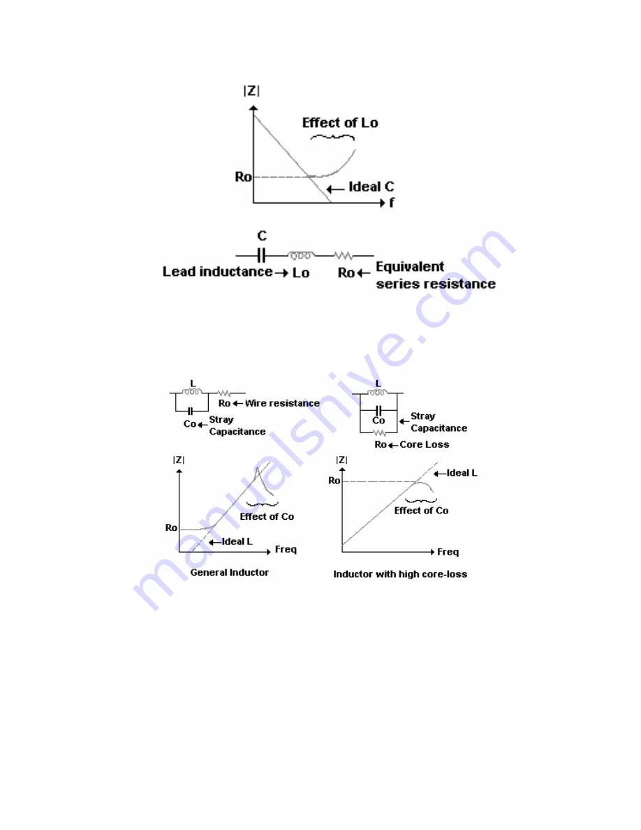
Page 13: ...dependency factors that affect measurement results 1 Frequency Frequency dependency is common to all real components because of the existence of parasites Not all parasites affect the measurement but...
Page 14: ...Figure 10 Capacitor frequency response Figure 11 Indicator frequency response 11...
Page 15: ...his dependency varies depending on the dielectric constant K of the material used to make the ceramic capacitor Figure 12 AC voltage dependency for Ceramic capacitor Cored inductors are test signal cu...
Page 16: ...acitor will vary depending on the DC bias voltage applied as shown in Figure 14 Figure 14 DC bias voltage dependency for Ceramic capacitor In the case of cored inductors the inductance varies accordin...
Page 17: ...e temperature coefficient is an important specification for resistors inductors and capacitors Figure 16 shows some typical temperature dependencies that affect ceramic capacitors with different diele...
Page 18: ...ts e g humidity magnetic fields light atmosphere vibration and time may change the impedance value For example the capacitance of high K type dielectric ceramic capacitors decreases with age as shown...
Page 19: ...es all measurement capabilities Auto balancing bridge method is a common impedance measurement method for low frequencies It use on this instrument provides increased accuracy while easing operation F...
Page 20: ...atic Recording for Maximum Minimum and Average reading 5 D Q Selects Dissipation factor Quality factor and Phase angle displays 6 FREQ Selects test frequency 7 RANGE AUTO Press this button to select m...
Page 21: ...e 100V 120V 220V and 240V at 50 60HZ W WA AR RN NI IN NG G To avoid damage the equipment use only specified fuse when change the power line voltage Please refer to following table SELECTOR LINE VOLTAG...
Page 22: ...ative mode indicator 6 MIN Minimum reading indicator 7 DH Data hold indicator 8 Phase angle indicator 9 Q Quality factor indicator 10 D Dissipation factor indicator 11 Secondary display 12 Beeper tone...
Page 23: ...mode indicator 23 Mk Resistance Ohm indicator 24 Inductance Henry indicator 25 Capacitance Farad indicator 26 RS232 indicator Special Indication Characters Indicates short connectors Indicates open co...
Page 24: ...t leave the instrument exposed to direct heat from the sun or other heat source for long periods Before removing the cover ensure that the instrument is disconnected from any circuit and in power OFF...
Page 25: ...to the component leads as required or use SMD Tweezers to measure SMD type component 5 Press FREQ button to select test frequency 6 Press D Q button to select Q factor for secondary display 7 Remove...
Page 26: ...optional SMD Tweezers to measure SMD type component 5 Press FREQ button to select test frequency 6 Press D Q button to select D factor for secondary display 7 Remove your hands from clips then read th...
Page 27: ...FORCE respectively 4 Connect the test clips to the component leads as required or use optional SMD Tweezers to measure SMD type component 5 Press FREQ button to select test frequency 6 Remove your han...
Page 28: ...ndicators will indicate what value is being displayed Whenever the MAX AVG MIN indicators appear on the LCD simultaneously the display reading is always a present value To exit this mode press and hol...
Page 29: ...rement Relative Mode Pressing the REL key enters the relative mode and stores the display reading as a reference value It will then display all subsequent readings relative to reference value Press th...
Page 30: ...10 and 20 tolerance as desire An audible tone of Beep Beep Beep will sound whenever the component under test exceeds set tolerance Conversely a single tone of Beep indicates the component is within th...
Page 31: ...e press and hold the AUTO button for more than one second Automatic Fuse Detection When the meter detects that the protective fuse is open the FUSE character will appear and an internal beep will soun...
Page 32: ...he ranges may be used for Parallel and Series modes The means the accuracy of ranges is specified for default measuring mode The dark areas are not provided on this meter 100Hz 120Hz 1KHz 10KHz Resist...
Page 33: ...100Hz 120Hz 1KHz 10KHz Inductance Range Series Parallel Series Parallel Series Parallel Series Parallel 1000H 200 100H 20H 2000 1000mH 200mH 20mH 2000 H Table 4 Inductance measurement 30...
Page 34: ...ector residues for further measuring It is highly recommended to calibrate extremely high or low ranges for L C and R before making precision measurements Calibration prompts will be displayed automat...
Page 35: ...th the text side facing up Connect the 9 pin connector to the communications port of a personal computer See the Figure 27 2 Press RS232 button to enable this interface You will find that the symbol o...
Page 36: ...ce mode 1 5 10 20 Test Signal Level 0 8Vrms approx Measuring Rate 1 time second nominal Response time Approx 1 second DUT device under test manual range Temperature Coefficient 0 15 x Specified Accura...
Page 37: ...0 199 99 0 5 3 After short cal 20 19 999 0 6 40 After short cal Test Frequency 1K 10K Hz Accuracy Range Maximum Display 1K Hz 10KHz Specified Note 10 M 9 999M 0 6 5 2 5 10 N2 After open cal 2000 K 199...
Page 38: ...9 99nF 0 4 5 DF 0 5 0 4 100 Cx 5 DF 0 5 After open cal 20nF 19 999nF 0 6 5 DF 0 1 1 100 Cx 5 DF 0 1 After open cal Test Frequency 1 KHz Accuracy Range Maximum Display Capacitance DF Spec Note 1mF 1 99...
Page 39: ...2 0 8 DF 0 1 4 0 100 Cx 8 DF 0 1 After open cal Notes 1 Q Value is the reciprocal of DF 2 DUT Device Under Test test lead should be used under properly shielding condition 3 Cx Counts of displayed C...
Page 40: ...0 Lx 10000 5 N2 5 100 Lx 5 After short cal Notes 1 For lower than 10 of range additional 10 digits should be added to the accuracy 2 The accuracy is specified for series mode in this range Test Frequ...
Page 41: ...5 100 Lx 10 20mH 19 999mH 0 6 Lx 10000 10 2 0 100 Lx 15 2000 H 1999 9 H 1 0 Lx 10000 10 5 0 100 Lx 20 After short cal Notes 1 Q Value is the reciprocal of DF 2 This specification is based on the meas...
Page 42: ...ACCESSORIES Standard Accessories Quick Start Guide User Manual in CD ROM 8cm Test alligator clips with BNC Pair See AC power cord Selection AC power cord 39...
Page 43: ...Optional Accessories RS232 Package Includes Optical cable CD ROM software Tenma Part 72 1026 SMD Tweezers 4 wire BNC Tenma Part 72 1027 40...
Page 44: ...ent parts only The meter must be completely turned off while replacing the fuse WARNING To avoid electrical shock or damaging the meter never allow water inside the case Cleaning the Meter Before clea...
Page 45: ...input voltage selector Selecting input line voltage Normally the fuse is provided with the proper rating of your area Be sure to replace with a suitable fuse if selecting a different line voltage usi...
Page 46: ...holder Fuse The desired voltage will be indicated on this window Figure 29 Selecting line voltage by Fuse holder 3 Put the fuse into inside fuse holder Be sure that the fuse rating is same as followi...
Page 47: ...user to replace the fuse While replacing the fuse the power of the meter must be disconnected 1 Pull out the handle slightly from each side and move it to the carrying position 2 Loosen screws with s...
Page 48: ...Fuse rating T 0 1A 250V Figure 31 Fuse location 45...