background image

TM

TM

Page <25>

V1.0

27/12/19

Newark.com/exclusive-brands
Farnell.com/exclusive-brands
Element14.com/exclusive-brands

C. Setting of RS232C Serial Ports

Default of RS232C serial port for communication is set as:
Baud Rate  19200
Start bit 

1

Stop bit 

1

Data bits 

7

Parity Odd

Important Notice : 

This data sheet and its contents (the “Information”) belong to the members of the AVNET group of companies (the “Group”) or are licensed to it. No licence is granted for 

the use of it other than for information purposes in connection with the products to which it relates. No licence of any intellectual property rights is granted. The Information is subject to change 

without notice and replaces all data sheets previously supplied. The Information supplied is believed to be accurate but the Group assumes no responsibility for its accuracy or completeness, 

any error in or omission from it or for any use made of it. Users of this data sheet should check for themselves the Information and the suitability of the products for their purpose and not make 

any assumptions based on information included or omitted. Liability for loss or damage resulting from any reliance on the Information or use of it (including liability resulting from negligence or 

where the Group was aware of the possibility of such loss or damage arising) is excluded. This will not operate to limit or restrict the Group’s liability for death or personal injury resulting from its 

negligence. TENMA is the registered trademark of Premier Farnell Limited 2019.

Summary of Contents for 72-1015

Page 1: ...TM TM Page 1 V1 0 27 12 19 Newark com exclusive brands Farnell com exclusive brands Element14 com exclusive brands Bench Digital Multimeter User Manual Part Number 72 1015 ...

Page 2: ...nspection Open the package case and take out the Meter Check the following items carefully for missing or damaged parts Item Description Qty 1 Operating Manual 1 piece 2 Test Lead 1 pair 3 Alligator Clip 1 pair 4 Multi Purpose Socket 1 piece 5 Point Contact Temperature Probe to be used under 230 C temperature measurement 1 piece 6 Power Cord 1 piece 7 RS232C Interface Cable 1 piece 8 Installation ...

Page 3: ... in an environment of high temperature humidity explosive flammable gas or strong magnetic field Do not use the meter if allowed to get wet Even after complete drying incorrect readings could occur causing a po tentially hazardous condition When using the test leads keep your fingers behind the finger guards Disconnect circuit power and discharge all high voltage capacitors before testing resistan...

Page 4: ...ds International Electrical Symbols AC or DC Ground Double Insulated Warning Refer to the Operating Manual Low Battery Continuity Test Diode Capacitance Test Fuse Conforms to Standards of European Union The Meter Structure see figure 1 Figure 1 1 LCD Display 2 Rotary Switch 3 Input Terminals 4 Functional Buttons ...

Page 5: ...rrent measurement range from 0 01A to 10 00A Functional Buttons Below table indicated for information about the functional button operations Button Operation Performed POWER Turn the power on and off LIGHT Turn the display backlight on and off SELECT Switches between AC and DC measurement Switches between continuity diode and resistance measurements Switches between frequency and Fahrenheit temper...

Page 6: ...ed range 9 Ω kΩ MΩ Ω Ohm The unit of resistance kΩ kilohm 1 103 or 1000 ohms MΩ Megaohm 1 106 or 1 000 000 ohms A mA µA A Amperes amps The unit of current mA Milliamp 1 10 3 or 0 001 amperes μA Microamp 1 10 6 or 0 000001 amperes V mV V Volts The unit of voltage mV Millivolt 1 10 3 or 0 001 volts F mF μF nF F Farad The unit of capacitance mF Millifarad 1 10 3 or 0 001 farads μF Microfarad 1 10 6 o...

Page 7: ...ows 1 Insert the red test lead into the terminal and the black test lead into the COM terminal If the measured value is less than 600mV insert the red test lead into mV terminal instead and press RANGE button to select manual range 600 0mV mode the LCD displays MANUAL and mV 2 Set the rotary switch to V press SELECT button to select DC or AC measurement mode 3 Connect the test leads across with th...

Page 8: ...nal andthe black test lead into the COM terminal 2 Set the rotary switch to an appropriate measurement position in μA mA or A press SELECT button to select AC or DC measurement mode 3 Connect the test leads in series with the object being measured The measured value shows on the display AC measurement displays True RMS value 4 Press AC AC DC button to measure AC DC current s true RMS Note If the v...

Page 9: ...easuring low resistances the test leads and internal wiring will add approximately 0 2Ω to 0 5Ω of error To obtain accurate readings in low resistance short circuit the test lead beforehand and record the reading obtained call this reading as X Then use the equation measured resistance value Y X accurate readings of resistance If Ω reading with shorted test leads is not 0 5Ω check for loose test l...

Page 10: ...e black test lead into the COM terminal 2 Set the rotary switch to Ω and press SELECT button to select measurement mode 3 Connect the test lead across with the object being measured The buzzer sounds if the resistance of a circuit under test is 70 the circuit is in good condition The buzzer does not sound if the resistance of a circuit under test is 70 the circuit is broken 4 The measured value sh...

Page 11: ...st a diode out of a circuit connect the Meter as follows 1 Insert the red test lead into Ω terminal and the black test lead into the COM terminal 2 Set the rotary switch to Ω and press SELECT button to select measurement mode 3 For forward voltage drop readings on any semiconductor component place the red test lead on the component s anode and place the black test lead on the component s cathode T...

Page 12: ...d value shows on the display Note The Meter displays a fixed value which is the distributed capacitor s value of the inside Meter To ensure accuracy it is necessary to subtract this value from the measured value when measuring small capacitor Multi purpose socket can be used instead of test leads Insert the capacitor being tested into the corresponding input terminal of the multi purpose socket Th...

Page 13: ...est lead into the COM terminal 2 Set the rotary switch to Hz0 F and press SELECT button to select Hz measurement mode 3 Connect the test leads across with the object being measured The measured value shows on the display Note When making frequency measurements the measured signal a must fall within the following voltage level When 10Hz to 1MHz 150m a 30 rms When 1MHz to 10MHz 300m a 30 rms When 10...

Page 14: ...be to the object being measured The measured value shows on the display after few seconds Note The testing environment must between 180 C to 280 C to ensure accuracy especially when measuring low temperature Different reading may be obtained when testing room environment under short or open circuit situation then short circuited reading shall be considered as the correct reading The included point...

Page 15: ...om the multi purpose socket and remove the multi purpose scoket from the input terminal Operation of Hold Mode Warning To avoid possibility of electric shock do not use Hold mode to determine if circuits are without power The Hold mode will not capture unstable or noisy readings The Hold mode is applicable to all measurement functions Press HOLD to enter Hold mode Press HOLD again to exit Hold mod...

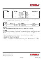
Page 16: ...rotary switch position V mV μA mA or A DC will be displayed when it is pressed under DC measurement mode Power Input Switch It is used to select AC 120V 60Hz or DC 6pcs of 1 5V battery R14 to power on the Meter It is located at the rear of the Meter Sleep Mode The meter will automatically enter the sleep mode after approximately 10 minutes of inactivity to preserve battery life The last value will...

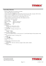
Page 17: ...ithout fuse protection Maximum Display Digital 5999 Measurement Speed Updates 2 3 times second Range Manual or auto ranging Polarity Display Auto Overloading Display OL Temperature Operating 00 C to 400 C 320 F to 1040 F Storage 10 0C to 500 C 140 F to 1220 F Relative Humidity 75 00 C 300 C below 50 30 400 C Altitude Operating 2000 m Storage 10000 m Below 1V m electrostatic discharge Accuracy spec...

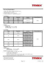
Page 18: ... all other ranges Around 10MΩ B AC Voltage Range Resolution Accuracy Overload Protection 600mV 0 1mV 40Hz 50kHz 0 6 5 1000V 50kHZ 100kHz 1 5 6V 0 001V 40Hz 1kHz 0 6 5 1kHz 10kHz 1 0 5 10kHz 100kHz 3 5 60V 0 01V 40Hz 1kHz 0 6 5 1kHz 10kHz 1 5 5 10kHz 20kHz 3 5 20kHz 100kHz 8 5 600V 0 1V 40Hz 1kHz 0 6 5 1kHz 10kHz 3 5 5 1000V 1V 40Hz 1kHz 1 2 3 1kHz 3kHz 3 3 Remarks Input Impedance At 600mV range Ar...

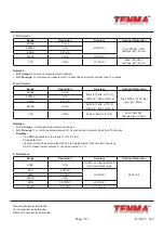
Page 19: ...Hz 1 5 10kHz to 15kHz 2 5 Fuse 500mA 125V fast type ɸ5 20mm 6000μA 1μA 60mA 0 01mA 600mA 0 1mA 40Hz to 10kHz 1 5 10kHz to 15kHz 3 5 10A 10mA 40Hz to 5kHz 2 6 Fuse 10A 250V fast type ɸ5 20mm Remarks At 5A range Continuous measurement is allowed At 5A range For continuous measurement 10 seconds and interval not less than 15 minutes Displays True RMS applicable to the range of 10 to 95 AC peak factor...

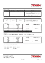
Page 20: ... Open circuit voltage approximate 2 7V Working current approximate 1mA H Capacitance Range Resolution Accuracy Overload Protection 6nF 0 001nF 2 5 5 250V rms 60nF 0 01nF 600nF 0 1nF 2 5 6μF 0 001μF 60μF 0 01μF 600μF 0 1μF 3 4 6mF 0 001mF 5 4 Remarks At 6nF 60nF and 600nF Range reading must subtract the test lead open circuit capacitance value I Frequency Range Resolution Accuracy Overload Protecti...

Page 21: ...Vce 2 2V bo 10μA 1000ᵦ MAX Maintenance This section provides basic maintenance information including battery and fuse replacement instruction Warning Do not attempt to repair or service your Meter unless you are qualified to do so and have the relevant calibration performance test and service information To avoid electrical shock or damage to the Meter do you get water inside the case A General Se...

Page 22: ...Fuse 2 and 3 Use a coin to open the accessories compartment at the top of the front cover then you will see a fuse compartment Open the fuse compartment to replace fuse 2 and 3 Remove the fuse by gently prying one end loose then take out the fuse from its bracket Then install the replacement fuse Fuse 4 It is located at the PCB Remove the fuse by gently prying one end loose then take out the fuse ...

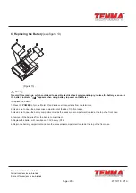
Page 23: ...o power on the Meter To replace the battery 1 Press the POWER to turn the Meter off and remove all connections from the terminals 2 Use a coin to open the accessories compartment at the top of the front case 3 Use a coin to open the battery compartment inside the accessories compartment located at the top of he front case 4 Remove all the batteries from the battery compartment 5 Replace the batter...

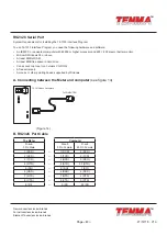
Page 24: ...er monitor Microsoft Windows 95 or above At least 8MB of RAM At least 8MB free space in hard drive Can access to a local or a network CD ROM A free serial port A mouse or other pointing device supported by Windows A Connecting between the Meter and computer see figure 14 72 1015 Back Faceplate To COMPUTER Figure 14 B RS232C Port Cable The Meter Computer D sub 9 Pin Male D sub 9 Pin Female D sub 25...

Page 25: ...ut notice and replaces all data sheets previously supplied The Information supplied is believed to be accurate but the Group assumes no responsibility for its accuracy or completeness any error in or omission from it or for any use made of it Users of this data sheet should check for themselves the Information and the suitability of the products for their purpose and not make any assumptions based...

Reviews: