

PLATFORM GUIDE
AIRWALL™-250 SERIES
Installation Instructions
Airwall™-250 Series
EN
DOC-0059
PLATFORM GUIDE
Revision Date: March 2, 2020
TROUBLESHOOTING
If an Airwall is online, you can use the Conductor user interface to download a packet capture file, a
diagnostic report, or a support bundle.
Troubleshoot an Airwall using packet capture:
Packet capture is one of several diagnostic tools that you can use to facilitate troubleshooting an
Airwall.
1. Select Airwalls and choose one from the list and click Diagnostics.
2. Begin packet capture by clicking Start Packet Capture and then stop packet capture by clicking
Stop Packet Capture.
Once the packet capture .pcap file has been created, you get a download link to the file. The .pcap
file is a standard format file that can be viewed using any packet-capture and protocol-analysis tool,
such as Wireshark.
Troubleshoot an Airwall by creating a diagnostic report:
Creating a diagnostic report is one of several diagnostic tools that you can use to get a general over-
view of the health of an Airwall.
1. Select Airwalls and choose one from the list and click Diagnostics. If the Airwall is offline, you
can put it into diagnostic mode and download a support bundle.
2. Create your report by clicking Request a diagnostic report.
Once the report .txt file has been created, you get a download link to it. The diagnostic report is a text
file that you can examine to see a high-level look at the overall health of the Airwall.
To create a support bundle:
1. Log in to the Conductor with a system administrator or network administrator account.
2. Select Airwalls and choose one from the list and click Diagnostics. If the Airwall is offline, you
can put it into diagnostic mode and download a support bundle.
3. Create an Airwall support bundle by clicking Request a support bundle. Once the support bundle
.pkg file has been created, you get a download link to the file. A support bundle .pkg file is an encrypt-
ed archive that facilitates technical support by Tempered only.
Send the support bundle as an email attachment to [email protected].
To provision an Airwall Gateway in diagnostic mode:
1. Configure a computer to use DHCP to obtain an IP address and netmask; then connect the com-
puter to port 2 of the Airwall.
2. Apply power to the Airwall.
3. Place the Airwall into diagnostic mode by pressing and holding the multi-purpose button for three
seconds. The status LED will display a fast blink pattern, as described in the blink patterns section of
this document. Caution: Do not continue pressing the multi-purpose button as this will factory-reset
the Airwall.
4. In your web browser, navigate to http://192.168.56.3. The diagnostic mode interface will load.
5. Click Configuration, and select Conductor URL.
6. Enter the Conductor URL in the Host field. Click Submit.
7. Reboot the Airwall by selecting the Actions drop-down and clicking Reboot or by turning the
power off and back on again.
To provision an Airwall using DHCP and a DNS SRV record:
For maximum scalability and flexibility, the DNS SRV record is the preferred connection type. The
Airwall will use the DHCP-provided search domain to create a DNS SRV query for the Conductor.
Note: Before you begin, ensure there is a DHCP server on your shared network and that a DNS
resolver or DNS server for the local domain is accessible from the shared network.
1. On the DNS server, add a SRV record pointing to the Conductor. SRV records have the following
format:
_service._proto.name TTL class SRV priority weight port target
If your shared network domain is example.com and the Conductor has hostname conductor-01, then
the SRV record should have the following values:
_ifmap._tcp.example.com. 3600 IN SRV 10 0 8096 conductor-01.example.com
The TTL, priority and weight should be determined by your DNS environment and are provided above
as an example. Port 8096 is the default, but you can change it in the Conductor and set it to an
alternate port.
2. Apply power to the Airwall
3. Connect port 1 on the Airwall to your shared network. An IP address, netmask, and a default
gateway are assigned to the Airwall from the DHCP server. The Airwall then does a DNS lookup and
configures itself using the Conductor address.
The Conductor is the central configuration and management point for all Airwall Edge Services.
For provisioning, an Airwall must be able to locate the Conductor on your shared network, either by
manually configuring the IP or URL in diagnostic mode, or by using a DNS SRV record that allows the
AIrwall Gateway to look up the address of the Conductor.
Provisioning the Airwall-250
Deployment Overview
An Airwall appears online in the Conductor user interface once provisioning is complete. An autho-
rized user can then log in to the Conductor, license and manage the Airwall, and then add it to an
overlay network, configure protected devices attached to the Airwall, and enable communication
between other Airwall Edge Services and protected devices. You use port 1 to connect the Airwall to
your shared network and ports 2-8 to connect your local devices.
Note: You can also reconfigure port assignments from the diagnostic web interface.
• The equipment must be installed in an enclosure that provides a degree of protection not less than
IP 54 in accordance with EN 60079-15 and accessible only by the use of a tool.
• Subject devices are for use in an area of not more than pollution degree 2 in accordance with EN
60664-1.
• Transient protection shall be provided that is set at a level not exceeding 140% of the peak rated
voltage value at the supply terminals to the equipment.
• This equipment is an open-type device that is to be installed in an enclosure only accessible with
the use of a tool, suitable for the environment.
• This equipment is suitable for use in non-hazardous locations only.
Special Conditions of Use
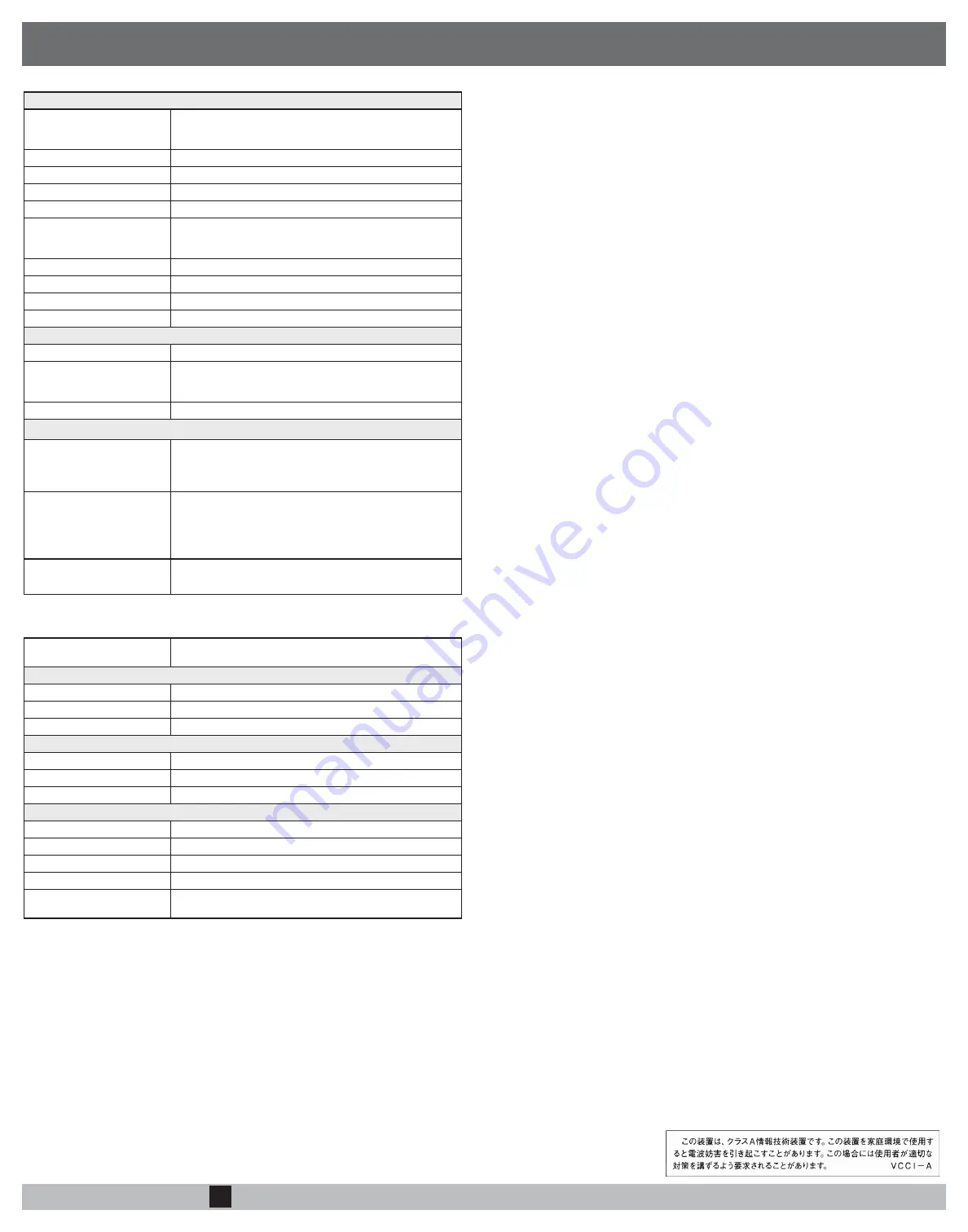
Airwall-250 Series
Ethernet Ports
4 x 10/100/1000 Mbps on RJ-45 ports, auto MDI/MDIX
4 x Combo 10/100/1000 Mbps on RJ-45 ports, auto MDI/MDIX
or 1 Gbps on SFP socket
Console Port
1x Micro USB
Power Input Failover
Automatic failover between all inputs
DC Power Input
Dual 12-48 VDC on terminal block
Storage Temp range
-40° to 85° C (-40° to 185° F)
Operating Temp range
-40° to 85° C (-40° to 185° F)
-30° to 70° C (-22° to 158° F) 3GPP Class A (cellular models
only)
Operating humidity
5% to 95%
Dimensions
188mm H x 188mm D x 130mm W (7.4" H x 7.4" D x 5.12" W)
Mounting
DIN-rail, wall-mount, or rubber feet
Weight
3.0 kg (6.61 lbs.)
Power-over-Ethernet (PoE)
Operating Mode
Auto mode
PoE Power Output
Ports 1-8: IEEE 802.3at/af
Max 30W/port
Pin 1/2,7/8(-), Pin 3/6,4/5(+)
Protection Features
Overload, surge, and short-circuit protection
Cellular module (Sierra Wireless HL7588) – Supported Bands
4g Cellular Modes
LTE: 1900(B2)/ 1700(B4)/ 850(B5)/ 700(B13)/ 700(B17) MHz
LTE Category 4
Downlink: 150 Mbps
Uplink: 50 Mbps
3.5g Cellular Modes
UMTS/HSDPA/HSUPA/HSPA+/DC-HSPA+: 1900(B2)/850(B5)
MHz
Data (HSPA+) rates:
Downlink: Up to 42 Mbps (HSDPA category 24) Uplink: Up to
5.76 Mbps (HSUPA category 6)
Cellular antenna connectors
2x SMA female connectors (250g)
4x SMA female connectors (250gd)
SIM card slot
1x externally accessible 3FF micro SIM card slot (250g)
2x externally accessible 3FF micro SIM card slots (250gd)
Serial Interface (Port 1)
Protocols
RS-232, RS-422, RS-485 (full and half duplex)
Connector
DE-9M
Isolation
2.5 kV minimum
Serial Interface (Port 2)
Protocols
RS-422, RS-485 (full and half duplex)
Connector
Terminal block
Isolation
2.5 kV minimum
Regulatory Approvals
CE (Airwall-250e only)
EN 62368-1:2014, EN55032:2012, EN 55024:2010
cETLus
UL 62368-1:2004 (2nd ed.), CSA C22.2 No 62368-1-14 (Ed. 2)
IEC
62368-1:2014 (2nd edition)
IC
ICES-3:2016 (Issue 6)
FCC
FCC Part 15B Class A”.
FCC Part 22H, Part 24E, Part 27 (for 250g/250gd only)
SPECIFICATIONS