background image

7

Pair 1

Pair 1

Pair 1

Pair 2

Pair 2

Pair 2

Pair 3

Pair 3

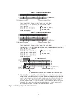
TYPICAL 2-CHANNEL CABLE WIRING

“Y” CABLE WIRING

TYPICAL 1-CHANNEL CABLE WIRING

Cable Type: 22AWG Stranded, 3-Pair Twisted-wire, with Shield

Pin 3: Channel 1 Audio / Power
Pin 4: Channel 1 Audio / Power
Pin 5: Channel 2 Audio / Power
Pin 6: Channel 2 Audio / Power

: Earth ground

Connector Type: 6-Pin XLR Audio (Neutrik only, not compatible with 6-pin Switchcraft)
Pin 1: Channel 1 & 2 Common
Pin 2: No connection

*

Shield

Cable Type: 22AWG Stranded, 2-Pair Twisted-wire, with Shield

Channel Audio / Power

Pin 3: Channel Audio / Power

: Earth ground

Connector Type: 3-Pin XLR Audio (Neutrik or Switchcraft)
Pin 1: Common
Pin 2:

*

Shield

*

Standard cables are generally constructed using a male connector at one end and a
female connector at the other end. This allows several cables to be interconnected to
create longer cable runs.

Audiocom power supplies use a 3-pin male Neutrik connector for

each channel. Audiocom wallplates use male Neutrik connectors.

Audiocom master stations, speaker stations and belt packs

also typically provide both a male and female Neutrik connector for each intercom
channel. This permits loop-through connection of several intercom stations using the
standard cables.

Use second drain wire if available, or add an extra section of wire.

Ch1

Ch2

Denotes twisted pair.

Denotes twisted pair.

Denotes shield.

Denotes shield.

3

3

3

3

2

2

2

2

1

1

1

Shield

Shield

Case

Shield

4

4

4

3

3

3

6

6

6

5

5

5

1

1 (Both wires)

1 (Both wires)

1 (Both wires)

Shield

Shield

Shield

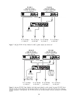
Figure 3

 - Cable Wiring Diagrams for Audiocom Applications.

Summary of Contents for Audiocom SPS-2001

Page 1: ...1 User Instructions Model SPS 2001 Power Supply 9350 7699 000 Rev A 4 2001 PS 2001L 1 2 SPS 2001 1 2 Volum e Model PS 2001L Power Supply Audiocom Intercom Systems ...

Page 2: ...comply with the limits of a Class A computing device pursuant to Subpart J Part 15 of FCC Rules which are designed to provide reasonable protection against such interference when operated in a commercial environment Operation of this equipment in a residential area may cause interference which the user at his own expense will be required to correct This product meets Electromagnetic Compatibility ...

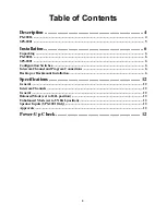
Page 3: ... Configuration Switches 6 Intercom Channel and Program Connections 6 Desktop or Rackmount Installation 6 Specifications 12 General 12 Intercom Channels 12 General 12 Balanced Mode set to BAL position 12 Unbalanced Mode set to UNBAL position 12 Speaker Inputs SPS 2001 Only 12 Approvals 12 Power Up Check 12 ...

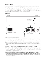
Page 4: ...e audio channel where all users can intercommunicate When in the Isolate position the unit will create two groups of completely independent users Channel Status Indicators The indicators are green for normal operation and red when there is an overload or short circuit The circuitry in the unit will automatically reset when the overload or short circuit is located and fixed Universal AC Power Input...

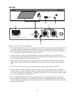
Page 5: ...nel Status Indicators The indicators are green for normal operation and red when there is an overload or short circuit The circuitry in the unit will automatically reset when the overload or short circuit is located and fixed Universal AC Power Input The unit accepts any input power in the range of 100 240 VAC 50 60 Hz Intercom Channel Connectors When the Combine Isolate switch is set to the Isola...

Page 6: ...tercom Channel and Program Connections Channel Capacity When connecting intercom stations to the PS 2001L or SPS 2001 determine the total current for all stations on each channel The total per channel should not exceed 2A If you exceed this limit an overload indication will be provided and the output of the power supply will be turned off Once the overload is corrected the overload indication will...

Page 7: ...enerally constructed using a male connector at one end and a female connector at the other end This allows several cables to be interconnected to create longer cable runs Audiocom power supplies use a 3 pin male Neutrik connector for each channel Audiocom wallplates use male Neutrik connectors Audiocom master stations speaker stations and belt packs also typically provide both a male and female Ne...

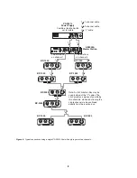
Page 8: ...ADSET LINES HEADSET LINES HEADSET LINES HEADSET LINES HEADSET LINES HEADSET LINES HEADSET LINES BP 1000 BP 1000 BP 1000 BP 1000 BP 1000 BP 1000 BP 2000 BP 2000 Note A JB 2 Junction Box may be used instead of the Y cables The JB 2 provides a means of combining two channels while also allowing the single channels to be continued directly from the junction box CH 1 BAL UNBAL CH 2 CLASS 2 WIRING 1 5A ...

Page 9: ...BP 1000 BP 1000 BP 1000 BP 1000 BP 1000 BP 1000 BP 2000 BP 2000 Note A JB 2 Junction Box may be used instead of the Y cables The JB 2 provides a means of combining two channels while also allowing the single channels to be continued directly from the junction box CH 1 BAL UNBAL CH 2 CLASS 2 WIRING 1 5A 24VDC 100 240 VAC 60 50 HZ TELEX COMMUNICATIONS INC MADE IN USA INPUT 1 SPEAKER INPUT 2 LINE LEV...

Page 10: ...Powered Speaker 1 1 1 Y Y 1 2 1 1 1 channel cable 2 2 channel cable Y Y cable 1 HEADSET LINES HEADSET LINES HEADSET LINES HEADSET LINES HEADSET LINES HEADSET LINES HEADSET LINES HEADSET LINES BP 1000 BP 1000 BP 1000 BP 1000 BP 1000 BP 1000 BP 2000 BP 2000 Note A JB 2 Junction Box may be used instead of the Y cables The JB 2 provides a means of combining two channels while also allowing the single ...

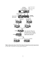
Page 11: ...X COMMUNICATIONS INC MADE IN USA INPUT 1 SPEAKER INPUT 2 LINE LEVEL 1 VRMS 12 15 VDC 1 SPEAKERS PROGRAM INPUTS 2 LINE LEVEL 1 VRMS P A EXP OUT CHN 2 VOL PGM 2 VOL PGM 1 BAL OUT UNBAL IN PUSH PUSH CHN 1 To of stations on channel 2 To of stations on channel 1 To of stations on channel 2 To of stations on channel 1 SPS 2001 Channel 1 Power Combine Isolate Switch set to Combine US2000A Internal DIP sw...

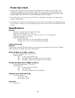
Page 12: ...tput Power each channel 21 1 VDC 2 A Dimensions 1 75 44 5 mm high x 8 25 209 5 mm wide x 10 31 261 9 mm deep Weight approximately 2 5 lb 1 13 kg Environmental Requirements Storage 20 C to 80 C 0 to 95 humidity non condensing Operating 0 C to 50 C 0 to 95 humidity non condensing Intercom Channels General Connector Type One XLR 3M audio connector for each channel Pin out depends on setting of BAL UN...

Page 13: ...R WHO SELLS TELEX PRODUCTS IS LIABLE FOR INCIDENTAL OR CONSEQUENTIAL DAMAGES OF ANY KIND CUSTOMER SUPPORT Technical questions should be directed to Customer Service Department Telex 12000 Portland Avenue South Burnsville MN 55337 U S A Telephone 952 884 4051 Fax 952 884 0043 RETURN SHIPPING INSTRUCTIONS Procedure for Returns If a return is necessary contact the dealer where this unit was purchased...

Reviews: