30 Maintenance
Airman 750/760 CMM
4.2.1 Testing the Circuit Board Assembly
To
test the circuit board assembly
, do the following:
1. Construct the test circuit. For more information, see Figure 4.
2. Connect the
circuit board
to the test circuit.
3. Remove the circuit board and wiring completely from the headset.
4. Set Vin to measure 0.47 mVAC, 1Khz, V
OUT
should read 297-592 mV,
when pot is set to midpoint.
If the output is outside this range, replace the circuit board. Specifications apply with
SW1 in both normal and reverse positions.
4.3 Speaker Validation
4.3.1 Speaker Sensitivity and Frequency Response Verification
Transducer Type:
Dynamic
Sensitivity:
(All Models) 104dB SPL ±5dB at 1kHz, 1mW input to headset,
at LOW volume control setting.
1mW based on input impedance of headset being tested.
Frequency
Response:
Must meet standards outlined in the specifications.
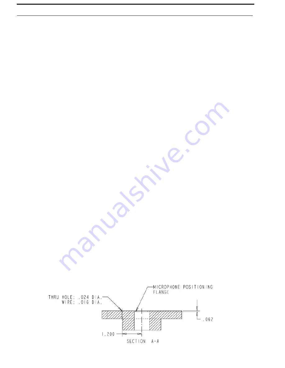
Earphone testing for the Airman 750 and 760 is done on a flat plate coupler.
For more information, see Figure 5.
To
measure the speaker
, do the following:
1. Calibrate a
lab microphone
.
2. Connect an
audio analyzer
to the lab microphone.
3. Place the
calibrated lab microphone
under the flat plate coupler and up through the
hole,
flush to the microphone positioning flange. (Use wire?) See Figure 5.
4. Place the
speaker (without the foam ear cushion or pad)
flush to the top of the flat
plate coupler, centered over the hole.
5. Use a
constant voltage sine wave generator
with a 50
output impedance to supply
the speaker with a 1mW, 1KHz signal to the appropriate connector. For more
information, see “Airman 750/760 Models and Connector” on page 8.
NOTE:
Once the headset/headphone is connected to the constant voltage
sine wave generator, the output voltage can be measured at the sine wave generator
or by the audio analyzer connected to the lab microphone.
FIGURE 5.
Flat Plate Coupler


