background image


15 


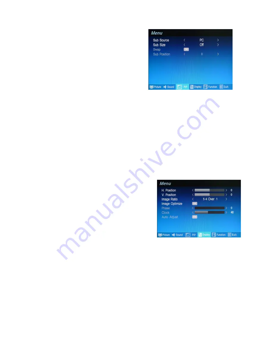
PIP (Video Mode)


Press the “Menu” key on the buttons to call out the OSD


“Menu” .  Press “

▲/+” or “▼/-“ 

to select 

“PIP” mode


and press 

“Menu” key again to select the “PIP” option. 


Sub Source 

Press the “Menu” key to enter the Sub Source and press  “

▲/+” or “▼/-“ 

to select PC as the sub-screen . 


Sub Size 

Press the “Menu” key to enter the Sub Size and press  “

▲/+” or “▼/-“ 

to select the size of sub-screen . There 

are 4 size to select (1).Small (2).Medium (3).Large  (4) PBP or select Off to close PIP setting. 
 

Swat 

Press  

▲/+” or “▼/-“ 

 key to enter the Swat and press  

“Enter”


to activate 

“OK” and


swat


the main screen and 

sub-screen. 
 

Sub Position 

Press the “Menu” key to enter the Sub Position and press  “

▲/+” or “▼/-“ 

to select 0~4 as the position of sub-

screen


0 : Top left  1: Bottom left  2: Central  3: Top right  4: Bottom right 


Display (Video Mode)


Press the “Menu” key on the buttons to call out the OSD 
“Menu” .  Press “

▲/+” or “▼/-“ 

to select 

“Display” mode


and press 

“Menu” key again to select the “Display” option. 


H-Position 

Use to change horizontal position of the picture. You may press 

▲/+” or “▼/-“

 key 

to select “H-Position” and  

press  

▲/+”

 key to increase 

“Blue bar” to shift the picture to right or press 

“▼/-“

 to decre

ase “Blue bar” to shift 

the picture to left. 


V-Position 

Use to change vertical position of the picture. You may press  

▲/+” or “▼/-“

 key 

to select “V-Position” and  

press  

▲/+”

  key to increase 

“Blue bar” to shift the picture up or press 

“▼/-“

 to decrease 

“Blue bar”  to shift the 

picture down. 


13 

Summary of Contents for TEL-22MR

Page 1: ...CCTV LCD Monitor User Manual For models TEL 22MR TEL 24MR ___________________________ English ...

Page 2: ...d Kingdom 4 3 Standards and Guidelines 5 3 1 FCC Requirements 5 3 2 FCC Warning 5 3 3 CE Conformity 5 3 4 RoHS Compliance Statement 6 3 5 Information on Disposal for Your Old Product 6 4 Hardware Installation 7 4 1 Checking the Accessories Supplied 7 5 Buttons and Connections 8 5 1 Buttons 8 5 2 Connections 9 6 ID Remote Controller 10 7 OSD Setup 11 8 Troubleshooting Guide 20 9 Applicable Video Ti...

Page 3: ...lug it in and it is ready for use 2 The monitor will accept and display analog video NTSC or PAL PC type video and Digital video sources 3 Low radiation and reduced flickering compared to traditional CRT monitors that minimizes eyestrain and health hazards 4 The compact size makes transportation easier and allows to use in many applications 5 This LCD monitor can support PC VGA Composite S Video H...

Page 4: ...ntained to ensure reliable and continued operation and to protect the LCD monitor from overheating Do not block ventilation slots and openings with objects or install the LCD monitor in a place where ventilation may be obstructed 6 Do not install this LCD monitor near a motor or transformer where strong magnetism is generated Images on the LCD monitor will be distorted and the color irregular 7 Do...

Page 5: ...irements and may look like this Figure A1 below Figure A1 Figure A2 2 3 1 For the United States and Canada In the United States and Canada the male plug is a NEMA5 15 style Figure A2 above UL Listed and CSA Labeled For units which are mounted on a desk or table SVT or SJT type cord sets may be used For units which sit on the floor only SJT type cord sets may be used The cord set must be selected a...

Page 6: ...Green and Yellow Ground Earth Blue Neutral Brown Live If the colored wires of the mains lead of this appliance do not correspond with the colored markings identifying the terminals in your plug proceed as follows The wire which is colored GREEN AND YELLOW must be connected to the terminal in the plug which is marked by the letter E or by the Earth symbol or colored GREEN or GREEN AND YELLOW The wi...

Page 7: ...Increasing the separation between the equipment and the receiver Connecting the equipment into an outlet on a circuit different from the one which the receiver is connected Consulting the dealer or an experienced radio TV technician for help Shielded interconnected cables and shielded power cords must be used with this equipment to ensure compliance with the pertinent RFD emission limits governing...

Page 8: ...ling of used electrical and electronic equipment When this corssed out wheeled bin symbol is attached to a product it means the product is covered by the European Directive 2002 979 EC If you wish to discard of this product please contact your local authorities and ask the correct method of disposal The coorect disposal of your old product will help prevent potenital negative consequences for the ...

Page 9: ...rocedures for the LCD monitor 4 1 Checking the Accessories Supplied LCD monitor body Desk Stand x 1 pc AC power cord x 1 pc Adaptor x 1 pc VGA 15 pin cable 1 8 Meter x 1 pc Ø 3 5mm audio line 1 5 Meter x 1 pc User manual CD x 1 pc Remote controller x 1 pc Battery AAA x 2 pc 7 ...

Page 10: ...urce will be shown in the following order PC HDMI AV1 AV2 S Video 2 To exit the menu when you finish the setting 3 Up Increase To move the cursor upwards or to switch over the setting items or to increase the figure of the setting selected 4 Down Decrease To move the cursor downwards or to switch over the setting items or to decrease the figure of the setting selected 5 Menu Enter To Enter the OSD...

Page 11: ... the Monitor 4 5 6 7 Composite Video Input and Output BNC type This Video input and output are used for CVBS input and output Thismonitor also supports the auto looping function permitting the connection of another monitor from the output connector 8 Stereo RCA Audio Input L R Stereo audio input R is right channel Red of audio connector L is the left channel White of the audio of connector PC Audi...

Page 12: ...and press to decrease volume DEFAULT Press Default to clear all the setting and return to factory default MUTE Press MUTE to mute the sound OSD setup a Press the MENU to enter the OSD menu and press UP or DOWN to select setting item and press RIGHT to increase or LEFT to decrease the blue bar to adjust the setting b Press the EXIT to exit the menu and confirm the setting c Press the ENTER to confi...

Page 13: ...in to select the Picture option 2 Various picture settings are available from the Picture menu Use or to select item that you want to adjust and press Menu key again until grey bar changes to blue color and press or increase or decrease the figure that you wish Press Exit key to return to menu and confirm the setting Press two times of Exit to exit all the menu Brightness Press or to increase decr...

Page 14: ...are six settings to choose from 1 Standard 2 Cold 3 Warm 4 User To select User you may press or to increase decrease the Blue bar to adjust color of Red Green and Blue Sound Video Mode 1 Press the Menu key on the buttons to call out the OSD Menu Press or to select Sound option and press Menu key again to select the Sound mode There are 2 sound modes to choose from 1 Standard 2 User 2 To select Use...

Page 15: ...s the Menu key to enter the Sub Position and press or to select 0 4 as the position of sub screen 0 Top left 1 Bottom left 2 Central 3 Top right 4 Bottom right Display Video Mode Press the Menu key on the buttons to call out the OSD Menu Press or to select Display mode and press Menu key again to select the Display option H Position Use to change horizontal position of the picture You may press or...

Page 16: ...ake the image fill up the 16 9 screen and cut about 2 on both Vertical and Horizontal lines 2 4 3 Over 1 The format is provide a true 4 3 format that will cut about 2 on Vertical and 2 on Horizontal lines 3 16 9 Over 2 The format is over scan mode to make the image fill up the 16 9 screen and cut about 4 on both Vertical and Horizontal lines 4 4 3 Full The format is the over scan mode that provide...

Page 17: ...d OSD Blend If you want to change the background color of OSD Menu you may press or key to select Background color Press Enter key and press or key to increase decrease the Blue bar the color will change from light blue to dark blue Sleep Time The function will make the monitor in sleep mode to save the power when monitor is in standby mode To press Enter to enter the option and press or key again...

Page 18: ...s Exit key to return to menu and confirm the setting Press two times of Exit to exit the menu Brightness Press or to increase decrease the Blue bar to adjust brightness Adjusting brightness to enhance the level of dark area in the video picture such as night scenes and shadow scenes Increasing brightness will make dark areas more visible Contrast Press or to increase decrease the Blue bar to adjus...

Page 19: ...ss Menu key again to Select the Display option H Position Use to change horizontal position of the picture You may press or key to select H Position and press key to increase Blue bar to shift the picture to right or press to decrease Blue bar to shift the picture to left V Position Use to change vertical position of the picture You may press or key to select V Position and press key to increase B...

Page 20: ... for best image setting Press Menu to enter OK mode To select the Auto Color The monitor will auto fine tune the color as default Phase Use phase to fine tune the monitor to perfectly ADC clock phase synchronize to the video signal source under RGB mode Press or to increase decrease the Blue bar to adjust the Phase Clock Use Clock to fine tune the monitor when phase value is wrong Press or to incr...

Page 21: ...21 Function PC HDMI Mode The setup is the same as page 15 for Function adjustment of Video Mode Exit Press the Menu key and press or to select Exit to exit the OSD menu 19 ...

Page 22: ... the front of LCD Monitor is in still green Check if the computer or AV equipment video signal cables are properly secured Abnormal image Check and make sure the computer or AV equipment video signal cables are properly and securely connected to the sockets on back of the LCD Monitor Abnormal image colors on the screen Check and make sure the LCD Monitor video signal cables are properly and secure...

Page 23: ... 000 SVGA 800 600 60Hz 37 879 60 317 40 000 SVGA 800 600 75Hz 46 875 75 000 49 5000 XGA 1024 768 60Hz 48 363 60 004 65 000 XGA 1024 768 70Hz 56 476 70 069 75 000 XGA 1024 768 75Hz 60 023 75 029 78 750 SXGA 1280 1024 60Hz 63 980 60 000 108 000 SXGA 1280 1024 70Hz 74 882 69 853 SXGA 1280 1024 75Hz 79 976 75 025 135 000 HDMI mode timing VESA MODES Horizontal Vertical Mode Resolution Nominal Frequency...

Page 24: ...24 10 Technical Data Specifications and product design are subject to change without notice 22 ...

Page 25: ...25 11 Dimension TEL 22MR TEL 24MR 23 ...

Reviews: