phone: (215) 947-2500 fax: (215) 947-7464 e-mail:[email protected] web site: www.televac.com
8/15
5
SENSOR OPERATION AND INSTALLATION
1.0
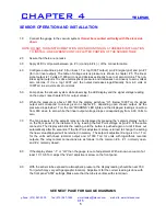
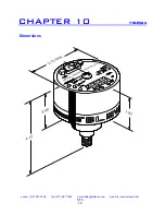
Connect the gauge to the vacuum system.
It must be mounted vertically with the stem side
down
.
NOTE: DO NOT TURN INSTRUMENTATION WHEN MOUNTING ON A THREADED INSTALLATION
TO INSTALL, USE A WRENCH ON THE FLATTED PORTION OF THE SENSOR TUBE
2.0
Assure that there are no leaks.
3.0
Apply 24 DC volt power between pin # 3 (+) and pin # 4 (-) of the connector cable.
4.0
Configure output lines; pin # 5 (for linear 1 T or log 1000T output), pin # 8 (signal gnd) and pin # 7
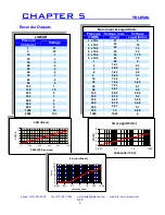
(for non linear output). The table of voltage versus pressure is shown in chapter # 5. The linear
signal output is 10 volts at 1000 microns and decreases linearly to zero at zero microns. The non-
linear signal output is 10 volts at atmospheric pressure and decreases non-linearly to zero volts at
zero microns. If it is a log 1000T unit, the output decreases logarithmically from 6.0 volts at
1000Torr to zero volts at zero microns.
5.0
Pump down the vacuum system while observing the LED display and the signal voltage reading
on the output. (see chapter # 5 for output values)
6.0
While the pressure is above 1000 Torr the display will show “HI”. Below 1000 Torr the signal
output will correspond to values given in chapter # 5, depending upon chosen output. As the
pressure drops below 1 Torr the red “MICRONS” LED lights and the displayed readings now drop
from 990 down to zero while the linear output voltage drops correspondingly from 9.90 Volts to
zero.
7.0
The trip pressure for the setpoint relay can be displayed by pressing the “setpoint display” button
on the front panel of the instrument or by reading the Set Point voltage at pin # 9 of the cable
connector. The display will blink the reading until the button is pushed again or until it times out
automatically after 60 seconds. If the Set Point adjustment screw is turned to change the setting
the new value displayed will be retained in memory. The setpoint adjustment range is 0 to 1 Torr
for the units with linear recorder output and 0-1000 Torr for units with logarithmic recorder
outputs. The relay contact connections are as follows; to the common # 6, # 1, normally open,
and # 2, normally closed.
8.0
If the display shows “-1” or “LO” then the gauge is out of adjustment. With a known vacuum of at
least 1 X 10⁻⁵ Torr, adjust the “Zero” adjustment screw on the front panel.
9.0
With the sensor tube exposed to atmospheric pressure, the display reading should be near 760
Torr (which may vary with geographic location). Adjustment for the correct reading is done with
the front panel “ATM” settings. Make sure that the tube is vertical, with stem down.
SEE NEXT PAGE FOR GAUGE DIAGRAMS
CHAPTER 4
TELEVAC


