4
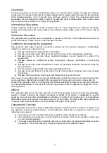
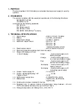
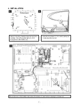
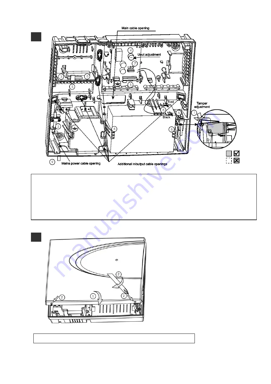
Adjust the tamper (1). Connect the mains cable, according to the sticker (2). Mount additional modules and
devices (3). Connect the output voltage to the devices and modules (5). Connect the tamper to the device
input, e.g. expander (8). The information outputs may also be used – “+I” for mains supply availability and
“+F “ for battery discharge. Mount and connect the battery. (6). Turn on the LED cable. (7). The LED will light
in red for Ubatt<10.5V. Turn on the mains (9). The LED should light in green.
Should it light in orange, leave
the battery to charge for at least one hour.
Where necessary adjust Uout. using the trimmer potentiometer (4).
5
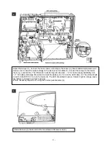
Place the cover (1) back and do the two screws at its lower end (2).
- 6 -
Summary of Contents for PS1210 12V 1A
Page 7: ...5 CONNECTION SCHEME 7 ...


