Telematics FP310RAM-X User Manual Download Page 8

General Description 

PROPRIETARY 

 1-3 


1-2.  General Description 

1-2.1  Purpose and Use  

The  FP310RAM-X  mini  reader  offered  by  Telematics  Wireless  is  a  versatile,  compact  and  reliable  unit 
that serves as the reader component of a vehicle identification system. Figure ‎1-1 shows a general view of 
the FP310RAM-X. 


Figure ‎1-1. FP310RAM-X, General View 

The  Telematics  Wireless  Mini  Reader  FP310RAM-X  is  a  reduced  version  of  Telematics  Wireless 
FP300RA  road  side  reader.  The  mini  reader  is  a  versatile,  compact,  and  reliable  unit  that  serves  as  an 
integral part of a vehicle identification system and may be used to read and write data to and from TDMA 
tags and to activates the tag's driver alert signal.  The  FP310RAM-X mini reader can be used for traffic 
load monitoring, gate pass applications, tag testing at point of sale and service and more.  

The FP310RAM-X may be operated from DC sources in the range of 9 to 30 VDC. It has low power drain 
(less than 0.3 W) and very compact size. 

1-2.2  Main Technical Characteristics 

The  FP310RAM-X  supports  two-way  communications  with  in-vehicle  transponders  (“tags”)  using  the 
ASTM  V6  Slotted-Aloha  Time  Division  Multiple  Access  (TDMA)  protocol.  The  physical  layer  is 
compatible with ASTM PS111-98. 

The FP310RAM-X communicates with transponders that enter its communication zone at speeds of up to 
125 mph (200 kph). The communication uses fixed transmit and receive frequency within the ISM band is 
used (915 MHz); the data rate is 500 kbps, with ASK modulation. The FP310RAM-X can use many types 
of antennas, to match the spatial resolution needed in the desired operation mode. 

1-2.3  Host Utility 

Telematics  Wireless  offers  a  dedicated  reader  host  utility  for  the  FP310RAM-X  that  can  be  installed  on 
any PC running Microsoft® Corp. Windows 2000 or XP. The FP310RAM-X connects to one of the free 
serial  communication  ports  of  the  PC  using  a  straight  modem  cable  (9  pin  to  9  pin).  The  host  utility 
provides full control over FP310RAM-X. 

1-2.4  Additional Equipment Needed 

The only additional accessories that have to be provided are: 


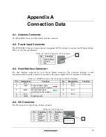
Antennas  of  a  type  suitable  for  the  specific  installation  requirements,  and  the  required  coaxial 

cables for connecting to the antennas. 

Summary of Contents for FP310RAM-X

Page 1: ...RWISE WITHOUT THE PRIOR WRITTEN PERMISSION OF TELEMATICS WIRELESS LTD NOR USED IN WHOLE OR IN PART FOR ANY PURPOSE OR FOR ANY CUSTOMER EXCEPT TELEMATICS WIRELESS NAME FP310RAM X User Manual DESIGNED M...

Page 2: ...interference in a residential installation This equipment generates uses and can radiate radio frequency energy and if not installed and used in accordance with the instructions may cause harmful int...

Page 3: ...s document contains proprietary information which is the sole property of Telematics Wireless The document is submitted to the recipient for his use only By receiving this document the recipient under...

Page 4: ...ion 2 2 1 2 1 General 2 2 1 2 2 Installation Requirements 2 2 1 2 2 1 Integration in Systems 2 2 1 2 2 2 Safety Considerations 2 2 1 2 2 3 Mechanical Data 2 2 2 2 3 Installation Guidelines 2 2 2 2 3 1...

Page 5: ...Figure 1 3 FP310RAM X Antenna Side Panel 1 1 4 Figure 2 1 FP 310RA Connections 2 2 1 Figure 2 2 FP310RAM X Mechanical Data 2 2 2 List of Tables Table 1 1 FP 310RA Connectors Indicators and Controls 1...

Page 6: ...1 3 1 2 2 Main Technical Characteristics 1 1 3 1 2 3 Host Utility 1 1 3 1 2 4 Additional Equipment Needed 1 1 3 1 2 5 FP310RAM X vs FP300RA 1 1 4 1 3 Physical Description 1 1 4 1 4 Functional Descrip...

Page 7: ...ion and describes the FP310RAM X mini reader functions and capabilities Chapter 1 Introduction Provides the information needed to plan the FP310RAM X installation and detailed installation instruction...

Page 8: ...al Characteristics The FP310RAM X supports two way communications with in vehicle transponders tags using the ASTM V6 Slotted Aloha Time Division Multiple Access TDMA protocol The physical layer is co...

Page 9: ...ensitivity Software controlled Fixed Protocol Report tag found Yes Yes Report tag lost Yes Yes Read Write to tag Multiple tags simultaneously Multiple tags simultaneously Agency programming Yes No Lis...

Page 10: ...ree operating modes Normal mode Mute mode and Maintenance mode 1 4 1 Normal Mode The functions performed by the FP310RAM X during operation in the normal mode are as follows Report the transponders th...

Page 11: ...2 1 2 2 3 Mechanical Data 2 2 2 2 3 Installation Guidelines 2 2 2 2 3 1 Power Requirements 2 2 2 2 3 2 Antenna 2 2 2 2 3 3 Communication Cables 2 2 3 2 3 4 Grounding and Lightning Protection Requirem...

Page 12: ...onic vehicle identification system Use the information appearing in Chapter 1 and Appendix A that covers the FP310RAM X interface characteristics and connection data to prepare cables in accordance wi...

Page 13: ...n at 12Vdc at an average power drain of 0 1W with instantaneous peak power of 0 3W A suitable power source must be provided as part of the installation The FP310RAM X does not have an ON OFF power swi...

Page 14: ...uld be run through grounded conduits to minimize external interference 2 3 4 Grounding and Lightning Protection Requirements All the FP310RAM Xs antenna mounting pole cabinet cable conduits and cables...

Page 15: ...nect if shell or pins are bent Thoroughly clean using a soft clean brush to remove dirt and foreign matter 3 Route each cable to the prescribed connector and mate the connectors For each D type connec...

Page 16: ...Installation Procedure 2 5 Chapter 3 OPERATION Contents 3 1 Scope 3 3 1 3 2 Power Up 3 3 1 Error Bookmark not defined...

Page 17: ...diation The FP310RAM X must not be allowed to transmit without being connected to antenna or to a suitable 50 load To apply power to the FP310RAM X 1 Check that power may be applied to the FP310RAM X...

Page 18: ...mmunication with the FP310RAM X 2 Connect a straight DB9 to DB9 modem cable between the host PC COM port and the host connector of the FP310RAM X 3 Start the host utility 4 After the PC establishes co...

Page 19: ...PROPRIETARY Appendix A CONNECTION DATA Contents A 1 Antenna Connector A 1 A 2 Power Input Connector A 1 A 3 Host Interface Connector A 1 A 4 I O Connector A 1...

Page 20: ...D type female connector The connector includes a serial asynchronous DCE interface used for connection to the host computer RS 232 interface 38400 baud Table A 2 HOST Connector Pin Functions for RS 23...

Page 21: ...PROPRIETARY...

Reviews: