


Telefire
ADR-3000 – System Introduction
Revision 1.10 4 November 2004
element, signal processing and two-way communication between the detector and the
control panel.
The TFH-220A heat detector can operate in either of two modes that can be configured
at the control panel:
•
F
IXED TEMPERATURE
mode – the alarm point is selected between 50°C – 90°C in
1°C increments (122°F to 194°F in 1.8°F increments).
•
C
OMBINED MODE
– rate of temperature rise and fixed heat detection. In this mode
the alarm threshold for the rate of temperature rise can be set between
7°C / minute and 13°C / minute (12.6°F / minute and 23.4°F / minute) and the
fixed temperature threshold is 60°C (140°F).
The ambient temperature, mode of operations, and alarm points can be observed at the
control panel using the Monitor Test menu.
Please refer to the TFH-220A technical manual for further details.
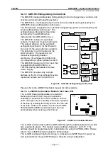
3.2.5 TFL-1NA Auxiliary Indicator for Analog Detectors
Telefire’s TFL-1NA Auxiliary Indicator for Analog Detectors enables auxiliary indication
for detectors that are located in hidden areas such as closed rooms and above acoustic
ceilings.
The remote Signaling Indicator is activated directly from the detector using the detection
line’s power without a need for auxiliary power sources.
The TFL-1NA can be connected to a single detector or to a group of detectors.
When activated, the Remote Signaling Indicator will flash both its LEDs alternately,
thereby drawing attention to a detector that is activated.
Please refer to the TFL-1NA technical manual for further details.
3.2.6 TFB-110A Common Base for Analog Addressable Detectors
The TFB-110A is a standard common base that enables connection between Telefire’s
plug-in analog detectors and a Telefire's analog addressable control panel. The base is
compatible with all of Telefire's Analog Addressable Detectors.
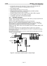
This base is intended for installation in acoustic or regular ceilings, allowing for SLC
(Signaling Line Circuit) loop wires and the optional TFL-1NA Remote Signaling Indicator
connections to be connected either vertically or horizontally.
Please refer to the TFB-110A technical manual for further details.
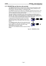
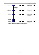
3.2.7 TPB-800ASR Manual Fire Alarm Call Point
The TPB-800ASR is an analog addressable call point push-button. It consists of a
standard alarm call point unit and an analog addressable interface module mounted
behind the front part of the break-glass section.
The address is assigned to the TPB-800ASR by using the PROG-4000 Programmer.
The TPB-800ASR is connected to the SLC loop in the same way as an analog detector.
3.2.8 TPB-800ASY Manual Extinguishing Call Point
The TPB-800ASY is an analog addressable extinguishing push-button.
It is mechanically and electronically identical to the TPB-800ASR, with the exception of
its bright yellow color to alert users that this is an extinguishing push-button rather than a
fire alarm push-button.
Both the TPB-800ASR and TPB-800ASY are configured as “push button”, but typically
they are configured so that pressing the TPB-800ASY manual extinguishing call point
activates the system extinguishers, whilst the TPB-800ASR is treated as an alarm.
– Page 11 –


