THCD-401 Instruction Manual
Page 10 of 47
3. Installation and Interconnections
This section contains the necessary steps to assist in getting a controller into operation as quickly and easily as
possible. Please read the following thoroughly before attempting to install the instrument.
Receiving Inspection
Prior to opening, inspect for obvious signs of damage to the shipment. Immediately advise the carrier who
delivered the shipment if any damage is suspected. If the shipment has arrived intact, carefully unpack the
gauge and any accessories that have been ordered. Check each component shipped with the packing list.
Ensure that all parts are present (i.e. gauge, power supply, cables, etc.). Optional equipment or accessories
will be listed separately on the packing list.
Mechanical Connections
The instrument is designed to be rack mounted. Note that the instrument must always be situated in such a
way as to enable adequate air circulation about the unit.
If a transducer was supplied with the THCD-401 a suitable cable may have been included.
NOTICE: The controller should be installed in a clean and careful manner. Take care not to drop the
product and avoid impacts to prevent damage.
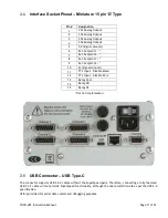
Transducer Socket Pinout – 15 pin ‘D’ Type (x4)
Pin #
Designation
2
Signal High
5
Signal Low (Signal Common)
6
-15 V Supply Output
7
+15 V Supply Output
8
Command Output (V)
9
Command Output (mA)
12
0 V Supply Common
13
+24 V Power Supply
15
Earth / Chassis
Other Not Connected
If the transducer is being powered from another source (e.g. a mains powered supply) it will only be necessary
to connect to the two signal pins.
NOTE: The THCD-401 ties 0V Power (pin 5) and Signal Low (pin 12) together. But the separate pins allow
large, power related currents to be routed separately from signal currents on long cables.


