


301/303/305/306/307 Flowmeters and Controllers Instruction Manual
EAR99 Technology Subject to Restrictions Contained on the Cover Page
Page 23 of 32
Symptom:
Output of flow meter is proportional to flow, but
extremely small and not correctable by span pot.
Cause:
Sensor is not being heated.
Action:
Shut off gas supply and disconnect the power to
the flow meter. Remove cover and PC board from
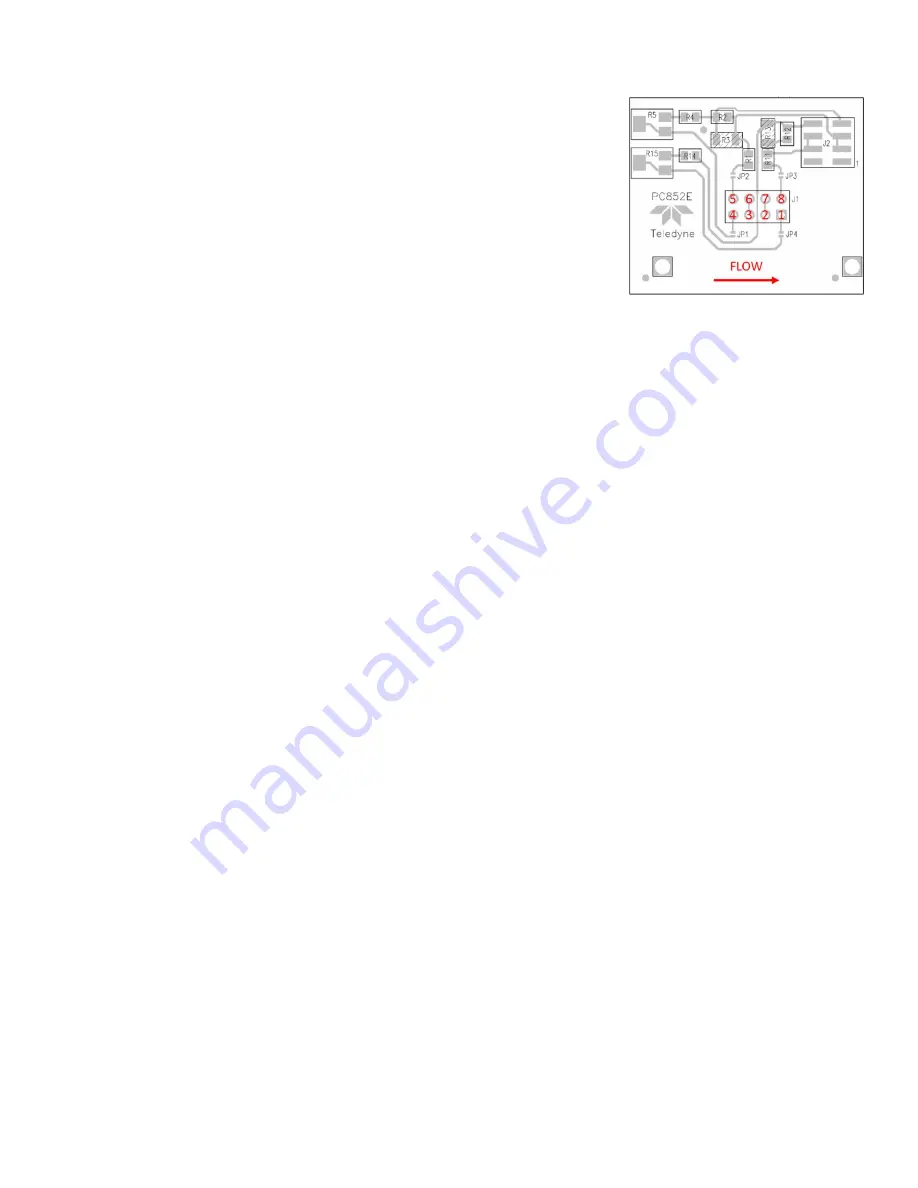
unit. Check the resistance from pins 1 to 2 and 3
to 4 of the sensor module. Both sets of pins should
read approximately the same value between 1 and
2 kΩ nominal resistance. Also check that the
resistance from pins 5 to 6, and 7 to 8 are both
nearly the same value between 200 and 400 Ω, See
Figure 3-1. Incorrect resistance values indicate
that the sensor unit needs to be replaced.
Symptom:
Sensor has proper resistance readings, but little or no output with flow.
Cause:
Plugged sensor.
Action:
Shut off gas supply and disconnect the power to the flow meter. Remove cover and
PC board from unit. Remove and inspect sensor. If sensor has evidence of clogging,
clean or replace as applicable.
Symptom:
flow meter reads other than 0.00 VDC with no flow or there is a small flow when the
flow meter reads 0.00 VDC.
Cause:
Zero pot is out of adjustment.
Action:
Shut off all flow. For the standard 0-5VDC output, adjust the zero potentiometer
located on the upper right inlet side of the flow meter until the meter indicates zero
(See figure in section 2.12). For the optional 4-20 mA output, adjust the zero
potentiometer so that the meter indicates slightly more than 4 mA, i.e. 4.03 to 4.05
mA. This slight positive adjustment ensures that the 4-20 mA transmitter is not in its
cut-off region. The error induced by this adjustment is approximately 0.3% of full
scale.
Symptom:
Flow meter is out of calibration and non-linear.
Cause:
Leaks in the gas inlet or outlet fittings.
Action:
Check all fittings for leaks by placing soap solution on all fittings between gas supply
and final destination of gas. Check flow meter for leaks. Replace or
recalibrate as necessary.
Symptom:
Little or no flow, even when the valve is overriden OPEN.
Cause:
Blocked orifice or incorrect pressure across the flow controller.
Action:
Verify that the pressure drop originally specified on the instrument is across the
instrument. If the differential pressure across the instrument is correct, the orifice
may be obstructed. If the orifice is suspected to be obstructed or blocked, it is advised
that the unit be returned to a qualified technician so the valve can be reworked.