Piranha HS-xx RoHS User Manual
Teledyne DALSA
03-032-20013-03
19
!
2.2.1 LED Status Indicator
The cam era is equ ip p ed w ith a red / green LED u sed to d isp lay the op erational statu s of
the cam era. The table below su m m arizes the op erating states of the cam era and the
corresp ond ing LED states.
When m ore than one cond ition is active, the LED ind icates the cond ition w ith the highest
p riority. Error and w arning states are accom p anied by corresp ond ing m essages fu rther
d escribing the cu rrent cam era statu s.
Table 3: Diagnostic LED
Priority
Color of Status LED
Meaning
1
Flashing Red
Fatal Error. Cam era tem p eratu re is too high and
cam era therm al shu td ow n has occu rred or a p ow er
on failu re has been d etected .
2
Solid Red
Warning. Loss of fu nctionality.
3
Flashing Green
Cam era initialization or execu ting a long com m and
(e.g., flat field correction com m and s
ccp
or
ccf
)
4
Solid Green
Cam era is op erational and fu nctioning correctly .
2.2.2 Power Connector
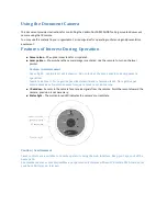
Figure 10: Hirose 6-pin Circular Male—Power Connector
Hirose 6-pin Circular Male
5
4
6
2
3
1
Mating Part: HIROSE
HR10A-7P-6S
The cam era requ ires a single voltage inp u t (+12 to +15VDC). The cam era m eets all
p erform ance sp ecifications u sing stand ard sw itching p ow er su p p lies, althou gh w ell -
regu lated linear su p p lies p rovid e op tim u m p erform ance.
WARNING: When setting up the camera’s power supplies follow these guidelines:
Ap p ly the ap p rop riate voltages
Protect the cam era w ith a
fast-blow fuse
betw een p ow er su p p ly and cam era.
Do not u se the shield on a m u lti-cond u ctor cable for grou nd .
Keep lead s as short as p ossible to red u ce voltage d rop .
Use high-qu ality
linear
su p p lies to m inim ize noise.
Use an isolated typ e p ow er su p p ly to p revent LVDS com m on m od e range violation.
Note: Camera performance specifications are not guaranteed if your power supply does not
meet these requirements.
Table 4: Hirose Pin Description
Pin
Description
Pin
Description
1
Min +12 to Max +15VDC
4
GN D
2
Min +12 to Max +15VDC
5
GN D
3
Min +12 to Max +15VDC
6
GN D
Summary of Contents for DALSA HS-80-08k40-xx-R
Page 16: ...Piranha HS xx RoHS User Manual 03 032 20013 03 Teledyne DALSA 16 ...
Page 84: ...Piranha HS xx RoHS User Manual 03 032 20013 03 Teledyne DALSA 84 ...
Page 108: ...Piranha HS xx RoHS User Manual 03 032 20013 03 Teledyne DALSA 108 ...
Page 110: ...Piranha HS xx RoHS User Manual 03 032 20013 03 Teledyne DALSA 110 ...
Page 116: ...Piranha HS xx RoHS User Manual 03 032 20013 03 Teledyne DALSA 116 ...
Page 120: ...Piranha HS xx RoHS User Manual 03 032 20013 03 Teledyne DALSA 120 ...