background image


Page | 7 


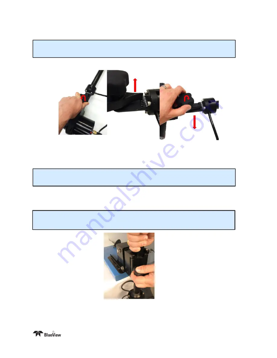
Tilt Angle Adjustment  


1.  Loosen the clamp angle adjustment knob by turning the knob counterclockwise. 


2.  Lift the clamp until the angle adjustment selector clears the angle keyway. 

3.  Select desired angle and tighten the angle adjustment knob by turning clockwise until it is snug.  

Pole Mounting 


1.  Securely attach the transom mount assembly to a fixed structure. The  mounting holes are sized 

for 1/4

” bolts. 

2.  Place the pole into the clamp and close the clamp by tightening the threaded knob.


3.  Rotate 

the  pole  in  the  mount  so  that  the  sonar,  when  set  to  the  ‘home  position,’  points  in  the 

desired direction. 

4.  In order to obtain accurate compass readings, ensure that the arrow on top of the unit is pointed 

parallel

 to the vessel centerline, in the direction of forward travel.


NOTE

It is the user’s responsibility to insure the pole mount is secured in a way that will 

support the pole assembly.


NOTE

It is the user’s responsibility to insure the pole mount is secured in a way that 

will support the pole assembly.


NOTE

Do not let go of the pole assembly until the clamp is closed and the threads have 

fully engaged.


Summary of Contents for BlueView BV3200

Page 1: ...e 0 User s Manual BV3200 Pole Mount Part Number 204765 00 Revision A October 2014 2014 Teledyne BlueView Technologies Inc All rights reserved All product names are trademarks of their respective companies ...

Page 2: ...x 8 Installing the Junction Box 9 Final Cable Connections 11 Install ProViewer 4 Software 11 Configure PC 12 Connecting the BV3200 GPS in ProViewer 4 12 Sonar Angle 15 ProMapper Add On Software 16 GPS Heading Compass Calibration 16 System Breakdown 17 Chapter 4 Maintenance 18 Before Use 18 After Use 18 Chapter 5 Troubleshooting 19 Still not working 20 Appendix A Technical Specifications 21 Appendi...

Page 3: ...his product contains lead a chemical known to the state of California to cause cancer birth defects and other reproductive harm Handling and or opening this unit may result in exposure to lead in the form of solder Warning Disassembly and repair of this electronic unit should only be performed by authorized service personnel Any modification of the serial number or attempt to repair the original e...

Page 4: ...a grounding plug The plug must be plugged into an outlet that is properly installed and grounded If repair or replacement of the cord or plug is necessary do not connect the grounding wire to either flat blade terminal The wire with insulation having an outer surface that is green with or without yellow stripes is the grounding wire Check with a qualified electrician or serviceman if the grounding...

Page 5: ...200 Transport Case Pole Assembly Junction Box Pole Mount 7 Ft Ethernet Cable USB Cable Power Cable BV3200 Software and Manuals CD Containing BV3200 QuickStart Guide BV3200 User s Manual ProViewer 4 Software ProViewer 4 Handbook USB Serial Adapter Driver Software Hex Driver Screw Kit Printed BV3200 QuickStart Guide ...

Page 6: ...le tilt angle integrated GPS and a compass The entire system connects through a single cable to the Junction Box which then connects to a PC via USB and Ethernet The BV3200 system is airline checkable luggage To familiarize yourself with the BV3200 system please review the information in this manual BV3200 unit in travel case BV3200 Components ...

Page 7: ...tions will walk you through all steps necessary to assemble the pole mount the sonar and connect all required cabling 1 Remove the BV3200 pole unit from case 2 Place the top and bottom pole pieces end to end Pull the sonar cable through the pole as you bring the pole bolt flanges together 3 Rotate one of the pole segments till the alignment notches are adjacent to each other ...

Page 8: ...ar and retightening the four cap screws 6 Connect the sonar cable to the sonar connector NOTE The sonar is inserted into the clamp such that its connector is on the same side as the Sonar Cable NOTE Use the stickers and connector placement on the rear end cap of the sonar or the logo on the front end of the sonar to determine the up down orientation of the sonar If the sonar is inverted be sure to...

Page 9: ...clamp by tightening the threaded knob 3 Rotate the pole in the mount so that the sonar when set to the home position points in the desired direction 4 In order to obtain accurate compass readings ensure that the arrow on top of the unit is pointed parallel to the vessel centerline in the direction of forward travel NOTE It is the user s responsibility to insure the pole mount is secured in a way t...

Page 10: ...verter adds a COM port to the PC so the PC can receive GPS data via a USB port The Ethernet port on the control box provides communication with the sonar The Sonar Junction Box can handle input AC power between 110 and 240 volts Ethernet Port to PC Sonar Communication To Pole Assembly USB Port to PC GPS and Compass Communication AC Power Inlet Port 110 240 VAC ...

Page 11: ...an available USB port on the PC connected to the internet The Found New Hardware Wizard will guide you through the automatic installation process 2 First the USB Serial Converter driver will install Select No not this time and click Next Follow prompts until the device is ready to use or cannot be installed NOTE Do not close the second Found New Hardware Wizard window while installing the driver N...

Page 12: ...evice Manager 4 In Device Manager under Other Devices right click USB HS Serial Converter and select Update Driver Software You will be asked how you want to search for driver software Select Browse my computer for driver software 5 Browse to the BV3200 CD J Box Drivers and select OK Click Next and follow screen prompts to complete driver installation ...

Page 13: ...s in the diagram below have been made 2 Connect the power cable to the control box Connect the opposite end to a suitable AC power outlet All necessary connections have now been made Install ProViewer 4 Software Whether connected to an external PC or an onboard AUV controller the ProViewer software is required to operate the M Series Sonar The following describes how to install the ProViewer 4 sof...

Page 14: ...ress automatically or to a static IP 192 168 1 x where x is any number besides 45 that doesn t conflict with the user s system Connecting the BV3200 GPS in ProViewer 4 General GPS to ProViewer 4 integration information is provided in the ProViewer 4 software manual The information provided below relates directly to establishing communications with the AIRMAR GH2183 GPS mounted inside the BV3200 Fo...

Page 15: ...mation on NMEA sequences refer to the ProViewer Software Handbook GPS Offset Because the GPS is mounted directly above the sonar on the BV 3200 the GPS offset will be zero for both x and y Current Configurations Once COM Port Settings NMEA Sequences and GPS Offset have been configured correctly you save a current configuration using the Add Current button The current configuration will appear high...

Page 16: ...displaying NMEA information on your ProViewer main window LAT LONG and Heading will be displayed in the lower right hand corner of your ProViewer 4 window Stop All Click this button to stop displaying NMEA information on your ProViewer main window ...

Page 17: ...both a better perspective on targets and a larger field of view of the bottom The BV 3200 allows the user to select any angle from 5 to 20 degrees in 5 degree increments The table below should be used as a guide for initial angle selection Target Depth ft 0 10 20 30 40 60 80 Approx Tilt Angle Deg 0 5 5 10 10 10 15 20 The sonar s steep tilt angle in this figure produces imagery of a narrow strip of...

Page 18: ...GPS unit mounted inside the BV3200 has an auto calibration feature which can be performed by following the steps outlined below IMPORTANT Calibration requires the vessel to complete 2 to 3 circles The compass should be calibrated to achieve maximum sensor accuracy Use of a timer or stop watch is recommended as the steps are time dependent Auto Calibration Procedure 1 Install the BV3200 on the vess...

Page 19: ... and pole cable be disconnected from the console rinse the pole and sonar with fresh water and return to their respective positions in the carrying case as shown NOTE Care should be taken to ensure cables are positioned not to crimp or damage pole components or the cable while shutting the case ...

Page 20: ...ll BV3200 hardware for excessive corrosion Replace as needed 3 Inspect all cables and connectors for abrasion cuts or cracks Repair or replace as needed After Use 1 After use rinse all BV3200 components with a solution of mild soap and fresh water At this time inspect all components for corrosion wear or damage Replace any piece of hardware showing corrosion or damage ...

Page 21: ...168 1 2 255 255 255 0 Sonar experienced a power glitch Unplug the AC power to the SPT Junction Box for 10 seconds and reconnect PC does not connect to GPS unit GPS Unit is not connected Verify the main pole cable is plugged into the Junction Box Verify the sonar connector is attached to the sonar Verify the Ethernet cable is connected to the Junction Box and the PC Verify the USB cable is connecte...

Page 22: ...Page 20 Still not working Please contact us BlueView Technologies Customer Support www blueview com 1 425 492 7376 8am 5pm PST Mon through Fri swa_support teledyne com ...

Page 23: ...y 1 per second GPS Fix Update Rate 2 x per second Pole Mount Pole Length Extended 77 5 in Pole Length Collapsed 47 5 in Cable Length 50 ft Electrical Power Supply 110 240 VAC 100 W max Mechanical Pole case weight 45 lbs BV 3200 Weight Without Sonar 15 80 lbs Pole case dimension 53 8 x 16 5 x 6 7 Recommended PC Specifications Processor 1 4 GHz Pentium M Memory 1GB DRAM Ports USB Ethernet Screen Sun...

Page 24: ...te TX 4 N C N C 5 N C N C 6 Green TX 7 N C N C 8 N C N C 8 Pin Connector to Sonar and GPS Unit Souriau UTG012 8S Pin Function A Ethernet RX to sonar B Ethernet RX to sonar C Ethernet TX to sonar D 24V DC E Ground F Ethernet TX to sonar G RS485A H RS485B 3 Pin C14 Power Connector Pin Function 1 110 240V AC 2 110 240V AC Ground 3 110 240V AC Common ...

Page 25: ...to sonar 2 Ethernet RX to sonar 3 Ethernet TX to sonar 4 24V DC 5 24V DC 6 Ethernet TX to sonar 7 Ground 8 Ground 9 N C 10 N C 8 Pin Connector to Sonar Burton 55R1 1508 Pin Function 1 Ethernet RX to sonar 2 Ethernet RX to sonar 3 Ethernet TX to sonar 4 24V DC 5 N C 6 Ethernet TX to sonar 7 Ground 8 N C ...

Reviews: