


23
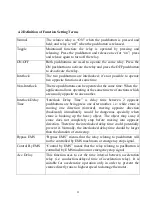
4-2 Definition of Function Setting Terms
Normal
The relative relay is “ON” when the pushbutton is pressed and
held; and relay is “off” when the pushbutton is released.
Toggle
Maintained function: the relay is operated by pressing and
releasing.
Press the pushbutton and release once for “on”; press
and release again to turn off the relay.
ON/OFF
Both pushbuttons are used to operate the same relay. Press the
ON pushbutton to activate the relay and press the OFF pushbutton
to de-activate the relay.
Interlock
The two pushbuttons are interlocked; it’s not possible to operate
two opposite functions at same time.
Non-Interlock
The two pushbuttons can be operated at the same time: When the
application allows operating at the same time two functions which
are usually opposite to one another.
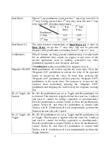
Interlock Delay
Time
“Interlock Delay Time” is delay time between 2 opposite
pushbuttons are being press one after another. i.e.: while crane is
moving one direction (forward), moving opposite direction
(backward) immediately would be dangerous specially when
crane is hooking up the heavy object. The object may sway if
crane does not completely stop before moving into opposite
direction. Therefore the interlocked delay time could potentially
prevent it. Normally, the interlocked delay time should be larger
than the duration of crane stop.
Bypass EMS
“Bypass EMS” means that the relay relating to pushbutton will
not be controlled by EMS mushroom or emergency stop signal.
Control By EMS
“Control by EMS” means that the relay relating to pushbutton is
controlled by EMS mushroom or emergency stop signal.
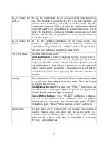
Acc. Delay
This function uses to set the time interval between acceleration
relay (i.e. conduction-delayed time of acceleration relay). It is
suitable for accelerative operation only in order to prevent the
cranes directly runs to highest speed to damage the motor.
Summary of Contents for F25
Page 1: ......
Page 2: ......
Page 11: ...8 4 2 F25 Receiver s parts Antenna Wiring Diagram Power On Indicator ...


