background image

16 

Function Setting 

Definition 

Interlock Delay Time 


“Interlock Delay Time” is delay time between 2 opposite pushbuttons are being 

press one after another. i.e.: while crane is moving one direction (forward), 
moving opposite direction (backward) immediately would be dangerous specially 
when crane is hooking up the heavy object. The object may sway if crane does 
not completely stop before moving into opposite direction. Therefore the 
interlocked delay time could potentially prevent it. Normally, the interlocked 
delay time should be larger than the duration of crane stop.


AFS 

First all, each channel group preset with 5 different channels.  

AFS (STD)

Auto Freq. Selection (Standard) 

The  remote  control  will  select  the  most  pure  channel  automatically  from  each 
Channel Group during operation.  
If  freq.  interference  occurs  during  operation,  the  remote  control  will  select  the 
next  most  pure  channel  automatically.    This  feature  makes  operating  free  from 
radio interference. 


“AFS (ECO)”

 -- Auto Freq. Selection (Power-Saving) 

The AFS (ECO) is a semi-auto frequency selecting system.   
If  freq.  interference  occurs  during  operation,  TX  has  to  be  rebooting  in  order  to 
select a new pure channel.    
AFS  (ECO)  is  the  factory  default  mode,  has  been  proved  to  meet  the  needs  of 
most users and with the battery efficiency advantages comparing to AFS (STD). 


“Single CH”

specified channel (freq.) for work 

The remote control will work in the specified channel only.


Channel 

There are total 32 groups with 160channels. Select the group from No. 1~32 
when using AFS or manually select single channel when AFS disable. 

Power-On Mode 

Any pushbutton/Start-Pushbutton/Password: 

Any pushbutton

: Pressing any button to power on the receiver. 

Start-Pushbutton

: Pressing 

START

 button to power on the receiver. 

Password

: The selection menu of key1, key2, key3, key4, Key5, and Key6 are 

popped up when Password is chosen. Allow the operator to select any 
combination of these 6 keys. Operator has to enter password before turning on 
the transmitter. The purpose is to prevent the unauthorized person from 
operating the remote controller or machine. 

Take & Release 

The receiver is available to be controlled by multiple users with maximum 15 
transmitters, but only one transmitter allows for controlling at a time (First-come, 
first-served). Free from other users radio interference after one taking control of 
the receiver. Press EMS button for releasing the control to others. 
(1)


Select Take & Release “Enable”


(2)


Select the transmitter from No. 1~15 or receiver for writing data. 

Note: Do not interchange the e-Card between transmitter and receiver when   
            

using “Take & Release” 


Summary of Contents for F24+ Series

Page 1: ...1 F24 Series Radio Remote Control User Manual ...

Page 2: ...medy If your TELECRANE product fails to work as warranted above TELECRANE maximum liability under this limited warranty is expressly limited to the lesser of the price you have paid for the product TELECRANE disclaims any liability as a result of any direct indirect special incidental or consequential damages Remarks No other warranty is expressed or implied except for the above mentioned Any use ...

Page 3: ...and has sufficient knowledge with safety precaution Although F24 transmitters are solid made for certain level of impact and weathering resistance but any malicious destruction or improper use might still cause high possibility of potential damage When transmitter battery power is low Red LED a STOP signal will be sent to receiver automatically to turn off receiver The batteries must be replaced i...

Page 4: ...e the Rotary KEY is on the OFF position 3 Turn on the transmitter Turn the EMS button clockwise and switch rotary key to ON position then press START button 4 Press function button for operation 5 To switch off the transmitter receiver please follow the procedure below a Press EMS button b Switch rotary key to off position and remove the KEY from transmitter c Remove the batteries when the equipme...

Page 5: ...Rotary Key and all other relevant functions Stop the operation immediately when any error occurs and resume to work until the error is being removed Transmitter LED Indicator Transmitter red LED indicator blinking Fast Pushbutton Jammed Power On without releasing EMS button Not correct Power On procedure Transmitter red LED indicator blinking Slow Low battery power replace new batteries immediatel...

Page 6: ...s Operating Temp 30 85 Operating Distance Up to 100 Meters Transmitter Power AA Battery x 4 Emission Power 10mW Pushbutton Single Double Steps Dimension 245x61x51 mm Weight Approx 255g without battery Receiver Power 1 24 36 42 48 110 220 230 380 VAC 50 60Hz tolerance 20 2 12 24VDC Sensitivity 110dbm Relay 5A 250VAC Dimension Approx 234x116x130 mm Weight Approx 1240g without cable ...

Page 7: ...ould be properly installed to prevent from loosing or dropping on the ground Check the power setting and relay configuration before installing the receiver Installing the receiver unit inside the control box is prohibited It is appropriate to install the receiver outside the control box F24 provides 4 3 billion sets of ID codes Each unit has a unique ID code address For safety reason please check ...

Page 8: ...g B Function Setting F24 remote control system can be set according to the working condition and operator s need for the following purposes Specific pushbutton function EMS neglected function Auto off time Interference neglected time etc This enables the remote controller to perform the most effective operation and to provide the safest operation Please refer to the Software Function Setting in Ch...

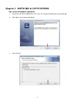
Page 9: ...apter 3 SOFTWARE COPY FUNTIONS F24 series PC Software Installation 1 Insert F24 CD into CD ROM Drive the auto run program will be pop up automatically 2 Click Next for continue installation 3 Click Install ...

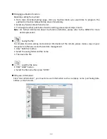
Page 10: ...staller_V 1 8 0 2 Double click PL2303 installer icon then the USB Driver program will be installed automatically How to use F24 series PC program Reading Writing the e Card 1 Before using F24 software check the COM port number which is being occupied by the USB cable You may find the COM port number from Control Panel System Hardware Device Manager ...

Page 11: ... Port Selection Select a COM port which USB cable is connected 4 Read e Card Setting 5 Writing to e Card Make sure the e Card has been inserting into the slot of USB interface cable Click Write Setting Click Finish completing the writing Note Do not remove or disconnect the USB cable during reading or writing ...

Page 12: ...on about the function definition please refer to the ANNEX for more detail explanation Saving the file To complete function setting and customer information of the remote please make a copy on your computer for after service and future data management 1 Click SAVE file button 2 Select the saving folder and file name 3 Then save the file Load the file data 1 Click LOAD button 2 Select the file name...

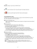
Page 13: ...N The transmitter has completed the e Card reading procedure LED blinking in RED Reading procedure is failed please repeat the procedure from step1 4 5 Turn the rotary key to OFF position Waiting for LED blackout take off the destined e Card Download e Card data Press EMS button and turn the rotary key to OFF position first 1 Insert the e Card which is destined to copy from the transmitter 2 Press...

Page 14: ... ON pushbutton and then press the Magnetic OFF pushbutton in the meantime The purpose is to prevent the operator from accidentally pressing the Magnetic OFF pushbutton and dropping the load held by the magnetic sucking disc ON OFF ON Two relative pushbuttons are set to control two relay outputs As these two pushbuttons work individual they are acting as Toggle However if these two pushbuttons asso...

Page 15: ...e is when you press the same button twice the relay still remains ON until another Group Toggle button is pressed This Feature also can be programmed for different application to setup a group of buttons to execute Toggle function Note Group Toggle is available from group 1 8 Interlock The two pushbuttons are interlocked it s not possible to operate two opposite functions at same time Normal Inter...

Page 16: ... mode has been proved to meet the needs of most users and with the battery efficiency advantages comparing to AFS STD Single CH specified channel freq for work The remote control will work in the specified channel only Channel There are total 32 groups with 160channels Select the group from No 1 32 when using AFS or manually select single channel when AFS disable Power On Mode Any pushbutton Start...

Page 17: ... to turn off the Transmitter after a given idle time while transmitting the STOP signal to switch off the receiver Only available under continuous transmitting mode e Card Copy Enable Disable Select Enable to unlock the e Card Read write protected for being duplicated by copier Or Disable to lock the e Card Read write protected for being duplicated by copier LED OFF Time This setting allows you to...

Page 18: ...elays go to OFF status The Main relay remains ON As long as the correct signal received again the remote function can be operated without rebooting 2 Power Off Shutdown It means that the Main relay will be OFF User need to reboot the remote control system to continue operating AUTO OFF RX User can set the receiver standby time exceeds the setting time then the receiver MAIN Relay will be turned of...

Reviews: