21
Theory of Operation
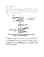
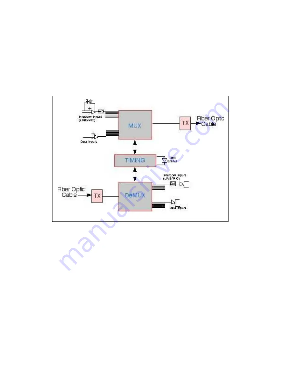
The Adder 882i circuit block diagram is shown in Figure 15. The unit has two
basic functions: multiplexing signals onto an optical fiber, and demultiplexing
signals from an optical fiber. The Adder 882i accepts up to ten intercom inputs,
eight digital inputs and four remote relay closures and time division multiplexes
them onto a single optical fiber.
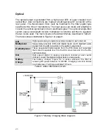
Figure 14: Electronics Block Diagram
All signals on the optical fiber are digital and, therefore, relatively insensitive to
transmission level variations. As a demultiplexer, the unit separates the
multiplexed signals it receives from the optical fiber and converts the audio
information back into analog signals. There is a one-to-one correspondence
between inputs and outputs at opposite ends of the system. Intercom inputs and
outputs are on their respective Intercom Modules located on the front panel.
Refer to Figure 1 on page 7.

