


16
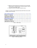
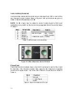
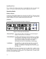
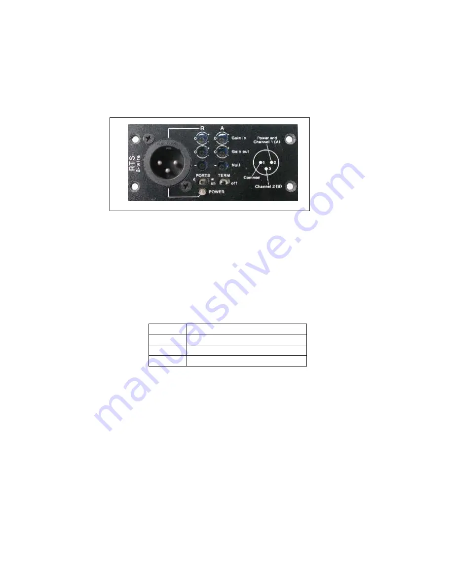
Table 5 lists the RTS/Telex pin numbers and intercom connections. Switches are
also provided for:
• Dry/unpowered (d), or Wet/powered (w) PORTS
• 200 W ON or OFF terminations TERM
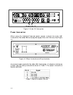
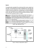
Figure 10: RTS 2-Wire intercom Module
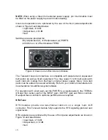
The interface is compatible with powered and unpowered belt packs as well as
fixed equipment. You may power 5 to 10 belt packs with each intercom module.
Refer to your intercom manufacturer’s documentation for additional system
details.
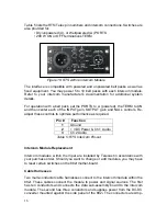
For operation with a belt pack, set the PORTS to w (powered), the TERM to ON
and then center each of the INPUT gain, OUTPUT gain and NULL controls. Re-
adjust these controls to optimize performance as required.
Pin #
Function
1
Ground
2
+ VDC Power & Ch.1 Audio
3
Ch.2 Audio
Table 5: RTS Intercom Pin-out
Intercom Module Replacement
Intercom modules within the Viper are installed by Telecast in accordance with
your purchase order. Should you want to change or add modules, you may have
to reset certain switches on the 882i mother-board.
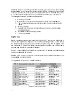
Cable Harnesses
Two multi-conductor cable harnesses connect to the intercom module within the
882i. These cables connect the module to power and signal sources. The first
has ten conductors and connects the data sub-assembly board to the intercom
module. The second has three conductors and supplies power from the DC-DC
converter mounted against the side panel of the 882i. The connectors are Amp-


