Teldat VisorALARM PLUS 2U Operating Instructions Manual Download Page 17


VisorALARM PLUS 2U

 Operating 

III - 10 

Doc.

DM375-I


Ver.

1.0


4.


Monitoring the receiver 

The VisorALARM PLUS 2U receiver includes monitoring capabilities  for the signal history log and 
account status that can be accessed and displayed through the keypad and the LCD display. 

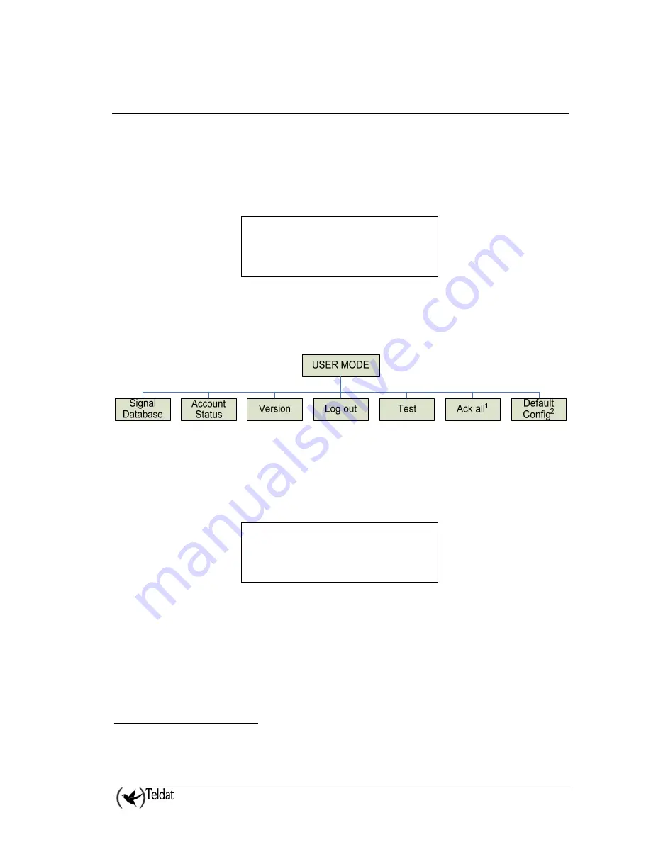
A User Mode menu is displayed by pressing the OK key on the keypad. If this is the first time the User 
Mode  menu  has  been  accessed,  the  receiver  prompts  the  user  for  a  valid  operator,  supervisor  or 
manager password. If a valid password is entered the LCD display will show a menu as follows: 


The 

ƒ

 and 

 keys let the user change the selected option enclosed in brackets. By pressing the OK 

key the receiver will show the selected option submenu. The full set of options in the USER MODE 
menu is shown in the next figure: 


Figure : User Mode root menu options 


When navigating by menus the 

 key goes back to the previous menu. If the menu is the USER 

MODE root menu the receiver exits the root menu and resumes normal or automatic operation of 
signals. 

The “Version” option shows the Receivers Version Identification as in the next figure: 


The “Log out” option resumes the receiver’s normal operation in such a way that the user must re-
enter a valid password to access the User Mode again. 

The “Test” option performs a test on the receiver Indicators (LEDs, LCD and Piezo Sounder) in order 
to verify the device is operating correctly. 

The “Ack all”

1

 option acknowledges all the signals pending acknowledgment. 

The “Default Config”

2

 option restores the VisorALARM PLUS 2U equipment to its factory default 

configuration. Please use this option only if you are fully aware and understand its reach and 
consequences. 


1

 Only for “Manager” and “Supervisor” users. 

2

 Only for “Manager” user. 


Software version: 
10.6.35 


      USER MODE     » 
{Signal Database} Acc 


Summary of Contents for VisorALARM PLUS 2U

Page 1: ...VisorALARM PLUS 2U Operating Instructions Doc DM375 I Rev 1 0 May 2007...

Page 2: ...ATORS 1 1 UNIT CONTROLS AND INDICATORS 2 1 1 LCD Display 2 1 2 LED Indicators 2 1 3 Keypad 3 1 4 Local Piezo Sounder 4 CHAPTER 3 OPERATING VISORALARM PLUS 2U 5 1 ACCESSING THE RECEIVER 6 2 OPERATING I...

Page 3: ...Chapter 1 System Overview...

Page 4: ...ally signal the reception of new signals It also provides specific function keys to manually acknowledge every received signal The IP VisorALARM PLUS 2U receiver operates together with the IP Module m...

Page 5: ...th both the main Teldat VisorALARM PLUS 2U as well as the backup if there is one As soon as this is re established with either of the VisorALARM PLUS 2U the mIP IPDACT will intercept the telephone lin...

Page 6: ...onfiguration patterns associated to installer passwords These permit you to automatically register new mIP IPDACTs in the supported mIP IPDACT list and at the same time enable the mIP IPDACT to reques...

Page 7: ...d also remotely telnet In both cases the access is restricted to users who are identified by a user name and a password Also the receiver can be monitored through a local console remotely through teln...

Page 8: ...Chapter 2 Controls and Indicators...

Page 9: ...line of the display shows the type of the receiver this can be PRIMARY BACKUP or Maintenance Receiver Second line shows the status of the receiver 1 2 LED Indicators LED Indicators are provided to ann...

Page 10: ...icator com2 not active Upload download communication in progress through com2 Upload download communication established through com2 1 3 Keypad The unit keypad includes 5 function keys and 12 addition...

Page 11: ...1 0 1 4 Local Piezo Sounder A piezo sounder provides distinct audible indications for alarm trouble and supervisory signals Signal Sound Alarm Sounds continuously Supervisory Sounds on and off at a h...

Page 12: ...Chapter 3 Operating VisorALARM PLUS 2U...

Page 13: ...n the figure The numeric keys must be used to introduce a valid numeric password for the system There are three privilege levels with different passwords to access the receiver The default receiver pa...

Page 14: ...be prompted for a password Upon entering the password the event with the highest priority is resounded Repeatedly pressing the ACK key will now display and acknowledge subsequent events Subsequently...

Page 15: ...e a signal the user must press the ACK key again If there are more pending signals the receiver shows the following And the user must press the ACK again in order to visualize the highest priority sig...

Page 16: ...signals are automatically sent to the Automation Software for acknowledgement Signals are also stored in the signal database for further review and the ACK and TRB LEDs still indicate alarm signals an...

Page 17: ...e User Mode root menu options When navigating by menus the key goes back to the previous menu If the menu is the USER MODE root menu the receiver exits the root menu and resumes normal or automatic op...

Page 18: ...ignal history log can be reviewed using different search criteria This option is described in depth in next paragraphs The Account Status option enters the ACCOUNT STATUS menu where the status and com...

Page 19: ...e The first four options represent different search criteria over the signal history database the option Info will display the total number of stored signals and the percentage of occupation The Clear...

Page 20: ...he Local Piezo Sounder Hdw failure Printer Printer not detected Network failure The device specified in the monitor_ip_address configuration parameter does not answer Probably the internet link is dow...

Page 21: ...3 E 4 F 5 The left key has the Clear function to delete previous digits and the ACK key clears all the digits When the account code is completed the user must press the OK key to validate the code As...

Page 22: ...tes are State Description Alive Device is all normal Supervision messages for the device are received as expected Registered Device is not connected Device is present in the Account Database but no me...

Page 23: ...rial Number 3 The Sw Rls option displays the mIP IPDACT device software release 4 The IP option displays the mIP IPDACT device IP address 5 The Port option displays the mIP IPDACT device UDP port Remo...

Page 24: ...VisorALARM PLUS 2U Operating III 17 Doc DM375 I Ver 1 0 NOTES...

Reviews: