


3.3.3 Connecting
• Make sure that the router’s power supply switch is in the OFF position (0).
• Ensure that the power supply is NOT connected to either the electricity supply
or the router.
• Connect all data cables.
• Connect the power supply cable to the device.
• Connect the power supply cable to the electricity supply.
• Place the router’s power supply switch in the ON position (1).
• Lower the safety cover.
3.3.4 Disconnecting
• Raise the safety cover.
• Make sure that the router’s power supply switch is in the OFF position (0).
• Disconnect the power supply from the electricity supply.
• Disconnect the power supply from the router.
• Disconnect the data cables.
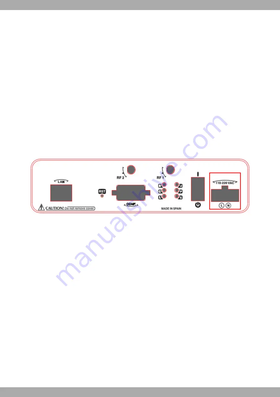
Fig. 10:
Power supply connector
The connector has 2 terminals for powering.
To connect the power to the device, please follow the steps indicated in
on page 13: check that the
power switch is in the OFF position (0) and that the power source is NOT connected to the electricity network; find
the Power Supply connector (located on the front panel) and insert the power cable connector.
3.4 RST button
There is a button labeled “RST” on the front panel of the Regesta PRO PLC router. This button has two functions.
• To trigger a restart.
• To restore the device to factory default settings. All switch ports are assigned with the factory default IP address
192.168.1.1.
The external button is physically protected to prevent it from being accidentally pushed. You will need to use a thin
pointed object to activate it.
3.4.1 Restarting the device
Follow the steps below to restart the device:
(1)
Press the RST button. Three LEDs (S, C and L) on the front panel light up in amber to indicate that the device is
in reset mode.
(2)
Stop pressing the RST button as soon as the three LEDs on the front panel are lit up.
(3)
The device will restart with the S and C LEDs unlit and the L LED in green.
Teldat S.A.
3 Components and power supply
Regesta PRO PLC
13


