Tekvox TEK MV71-4K 79064 User Manual Download Page 47

  47 / 49 


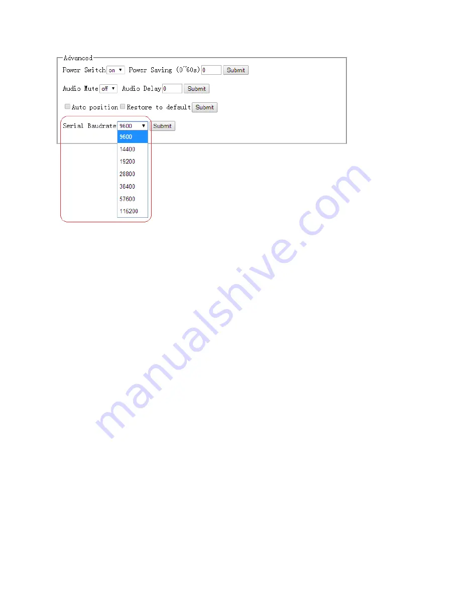
For the Serial baud rate setting, it is recommended that you use 9600. Select the related parameters, 
and click 

Submit

 to let the changes take effect. 


Other 

F/W Update 

The MV71 can be updated through a USB drive as follows. 

1)  Copy the updated file MERGE.bin to the root directory of the USB drive. 
2)  Connect the USB drive to the USB port on the rear of the device. 
3)  Connect the HDMI display to the MV71. 
4)  Turn on the MV71. The display device displays the HDMI output signal after normal boot of the 

device. 

5)  Press  and  hold  the  INPUTS  1  button  for  more  than  five  seconds,  "System  upgrading

"is 

displayed in the display device, at the same time, all the button indicators on the front panel 
will blink. 

6)  After updating, the device reboots automatically. 
7)  Turn off or restart the device after the red indicators on the panel are off, and the updating is 

completed. 


Summary of Contents for TEK MV71-4K 79064

Page 1: ...1 49 4K 7x1 Multiviewer Switcher TEK MV71 4K 79064 79065 User Manual All Rights Reserved Revised July 1 2015...

Page 2: ...ion may be copied or reproduced without prior written consent FCC Statement This equipment generates uses and can radiate radio frequency energy and if not installed and used in accordance with the in...

Page 3: ...product near water l Do not put any heavy items on the extension cable in case of extrusion l Do not remove the housing of the device as opening or removing housing may expose you to dangerous voltag...

Page 4: ...a single window outputting to a display device through one HDMI output l Supports pre defined multiple window mode l Supports breakaway audio l HDCP compliant l Fast switch between input ports l Supp...

Page 5: ...rating 12 Standby Mode and Operational Mode 12 Screen layout Configuration 12 Single Window 15 Double Windows 16 Triple Windows 17 Quadruple Windows 18 Output Resolution 19 Audio Setting 19 Audio Inpu...

Page 6: ...Read EDID Data from EEPROM 39 Read EDID Data from Output 39 Copy EDID Data from Output 39 WEB Setting 40 General Settings 40 Screen Layout Selection 41 Video Input Selection 41 Aspect Ratio 41 Audio...

Page 7: ...Button and Indicator Presses the buttons 1 4 indicating the corresponding windows are selected The indicators mean whether this window is effective 5 Video Window Mode Button and Indicator Video windo...

Page 8: ...5 Analog audio input 1 7 7 channel stereo analog audio input Connect a 3 5mm mini stereo cable from the Line Out jack on the audio source to this jack 6 HDMI input 1 4 Connect up to four Hi Def sourc...

Page 9: ...ss 1 7 buttons to select the corresponding window for select video input 4 Screen Layout Press this buttons to select Single mode Double mode TRIPLE mode and Quadruple mode 5 Audio Press this button a...

Page 10: ...rts of Multiviewer Switcher using the HDMI cables Installation How to Connect the Multiviewer Switcher 1 Connect up to four 4K or HD HDMI sources to the input ports HDMI 1 HDMI 4 Connect up to two 4K...

Page 11: ...to the Line In jack of a multimedia system or connect an optical cable from the OPTICAL on the Multiviewer Switcher to the Optical In of a multimedia system 6 OPTIONAL Connect an RS 232 cable from th...

Page 12: ...iewer Switcher and the AC outlet In Standby mode the Standby indicator will light up until the Multiviewer Switcher wakes up When the normal work mode is used the Standby indicator will turn off There...

Page 13: ...o 1 4 indicators will light up The Multiviewer Switcher can display up to four sources When multiple sources are displayed on the screen each source is regarded as a single window and each window is d...

Page 14: ...14 49...

Page 15: ...thod 1 Press the INPUTS 5 button on the front panel or remote Method 2 Press the Video 1 button on the front panel or remote The 1 button indicator on the panel will turn solid and the 2 7 button indi...

Page 16: ...d 1 Press the INPUTS 5 button on the front panel or remote The Video 1 and 2 button indicators will blink this indicates that the two buttons can be selected Press the Video 1 button on the front pane...

Page 17: ...witch to Window 1 and the DisplayPort5 signal Method 1 Press the INPUTS 5 button on the front panel or remote The Video 1 and 2 button indicators blink indicates the two buttons can be selected press...

Page 18: ...ndows are shown as follows 3 If you want to switch to Window 1 switch the signal of DisplayPort5 use one of the following methods Method 1 Press the INPUTS 5 button on the front panel or remote the Vi...

Page 19: ...0P 720P WUXGA UXGA WXGA XGA Auto When a resolution is selected the corresponding indicator lights up and the HDMI output is switched to the new resolution Audio Setting The MV71 supports breakaway aud...

Page 20: ...selected When the Input indicator of the corresponding audio source turns solid the other indicators blink 2 Press the desired Inputs button and the audio will switch to this channel At the same time...

Page 21: ...io format is stereo then audio output is used If the audio format is 5 1 then channels from 1 to 6 output the audio OSD Setting Instructions The On Screen Display OSD will show when inputs or volume l...

Page 22: ...22 49 C When the triple windows are displayed...

Page 23: ...23 49 D Quad windows 3 Audio Mute indicates 4 Volume adjustment 5 VGA Auto Menu...

Page 24: ...24 49 6 IP address...

Page 25: ...RS 232 port Connect to RXD TXD GND only RS 232 Settings Description Setting Baud rate 9600 Data bits 8 Parity None Stop bits 1 Hardware flow control None Notes For more information about serial comma...

Page 26: ...ber via the information from the OSD Whether MV71 is in single window mode or in multiple window mode IP address and port number can always be obtained from Window 1 When there is no signal the follow...

Page 27: ...that the PC and MV71 are in the same network segment Click Search The following device list is shown Select the device and click Setup The IP information is obtained from the Device Info page IP 192...

Page 28: ...e commands from RS232 or IP The command contains the following Source Control Advanced Control EDID Management Command header ATM Length 255 Command xxxxxxx Read Write W R Parameter data xx N byte Car...

Page 29: ...4 ATM 0A VDO_IPT W 2 4 Video input of Window 2 is set to 4 Select input 5 ATM 0A VDO_IPT W 2 5 Video input of Window 2 is set to 5 Select input 6 ATM 0A VDO_IPT W 2 6 Video input of Window 2 is set t...

Page 30: ...elect ext audio on input 3 ATM 0A AUD_MOD W 3 1 Set external audio on input No 3 Select ext audio on input 4 ATM 0A AUD_MOD W 4 1 Set external audio on input No 4 Select ext audio on input 5 ATM 0A AU...

Page 31: ...FULL ATM 0A WIN_RAT W 2 2 Set the picture in Window 2 to fill the entire window 16 9 ATM 0A WIN_RAT W 2 3 Set the picture in Window 2 as the 16 9 aspect ratio 4 3 ATM 0A WIN_RAT W 2 4 Set the picture...

Page 32: ...lution as 1600X1200 60Hz UXGA 1280X800 60Hz WXGA ATM 09 OPT_TIM W 7 Sets the HDMI output resolution as 1280X800 60Hz WXGA 1024X768 60Hz XGA ATM 09 OPT_TIM W 8 Sets the HDMI output resolution as 1024X7...

Page 33: ...n it s VGA it adjusts image position automatically OSD control Audio OSD on off ATM 09 AUD_OSD W 0 Turn on off the audio volume and mute OSD 0 audio OSD on 1 audio OSD off Video OSD on off ATM 09 VDO_...

Page 34: ...s on HDMI output ATM 08 HDO_HDP R Read Check the HDCP switch status on the HDMI output port Check the HDMI output timing ATM 09 HDO_EDI W 1 Read Check the timing of HDMI output port Check the HDBT out...

Page 35: ...or EDID data can be captured or loaded into ROM and copied to each input The simplest method is to use the built in preset EDIDs and assign them to an input Example Assign preset EDID to input port Se...

Page 36: ...M 0B EDI_POR W 4 C 1 Copy the preset EDID 1 in the program to port 4 2 ATM 0B EDI_POR W 4 C 2 Copy the preset EDID 2 in the program to port 4 3 ATM 0B EDI_POR W 4 C 3 Copy the preset EDID 3 in the pro...

Page 37: ...E 2 Copy the EDID of the EEPROM 2 to port 3 3 ATM 0B EDI_POR W 3 E 3 Copy the EDID of the EEPROM 3 to port 3 4 ATM 0B EDI_POR W 3 E 4 Copy the EDID of the EEPROM 4 to port 3 5 ATM 0B EDI_POR W 3 E 5...

Page 38: ...TM 13 EDI_NAE W 1 4K2K_8CH_1 Interior EDID 1 name write 2 ATM 13 EDI_NAE W 2 4K2K_8CH_2 Interior EDID 2 name write 3 ATM 13 EDI_NAE W 3 4K2K_8CH_3 Interior EDID 3 name write 4 ATM 13 EDI_NAE W 4 4K2K_...

Page 39: ...from input port 5 Read EDID of input 6 ATM 09 EDI_POR R 6 Read EDID from input port 6 Read EDID of input 7 ATM 09 EDI_POR R 7 Read EDID from input port 7 Copy EDID Data from Output EDID copy Copy EDID...

Page 40: ...For more information about how to obtain the IP address see the chapter IP Setting above For example the obtained IP address is 192 168 3 5 and port number is 23 Input http 10 0 0 10 in the address ba...

Page 41: ...he related parameters and click Submit to let the changes take effect Video Input Selection Video inputs W1 W4 correspond to the video inputs of the four windows The Video selection ranges from 1 to 7...

Page 42: ...cture in Window 1 as the 16 9 aspect ratio 4 3 Set the picture in Window 1 as the 4 3 aspect ratio Select the related parameters and click Submit to let the changes take effect Audio Input Audio input...

Page 43: ...43 49 Audio Volume Output volume ranges from 0 to 10 O is mute and 10 is the maximum volume Select the related parameters and click Submit to let the changes take effect Output Timing...

Page 44: ...changes take effect Advanced Settings Advanced settings contain the following options 1 Power Switch Selection 2 Power Saving Selection 3 Audio Mute Selection 4 Audio Delay Selection 5 Auto Position S...

Page 45: ...min and 60 min 0 is off meaning that this turns the function off Select the related parameters and click Submit to let the changes take effect Audio Mute Selection Audio output mute setting OFF turns...

Page 46: ...en VGA is input perform this function to automatically adjust the VGA picture Adjustment parameters contain Horizontal Position Vertical Position Clock and Phase At the same time OSD prompts the relat...

Page 47: ...he USB port on the rear of the device 3 Connect the HDMI display to the MV71 4 Turn on the MV71 The display device displays the HDMI output signal after normal boot of the device 5 Press and hold the...

Page 48: ...reen backlight Output Resolution Indicators 8 x LED green Power Indicator 1 x LED red Connectors Video Input 4 x HDMI Type A 19 pin female 2 x DisplayPort Full Size 20 pin female 1 x VGA DB 15 15 pin...

Page 49: ...s 4HDMI 2DP 1VGA YPbPr 4HDMI 2DP 1VGA YPbPr Video Outputs 1HDMI 1HDMI HDBase T Audio Inputs 7 aux unbalanced stereo 7 aux unbalanced stereo Audio Outputs 7 1 unbalanced analog and optical program audi...

Reviews: