background image


www.tekvox.com 

MV71-4K 

79064 User Manual 

1. Getting Started


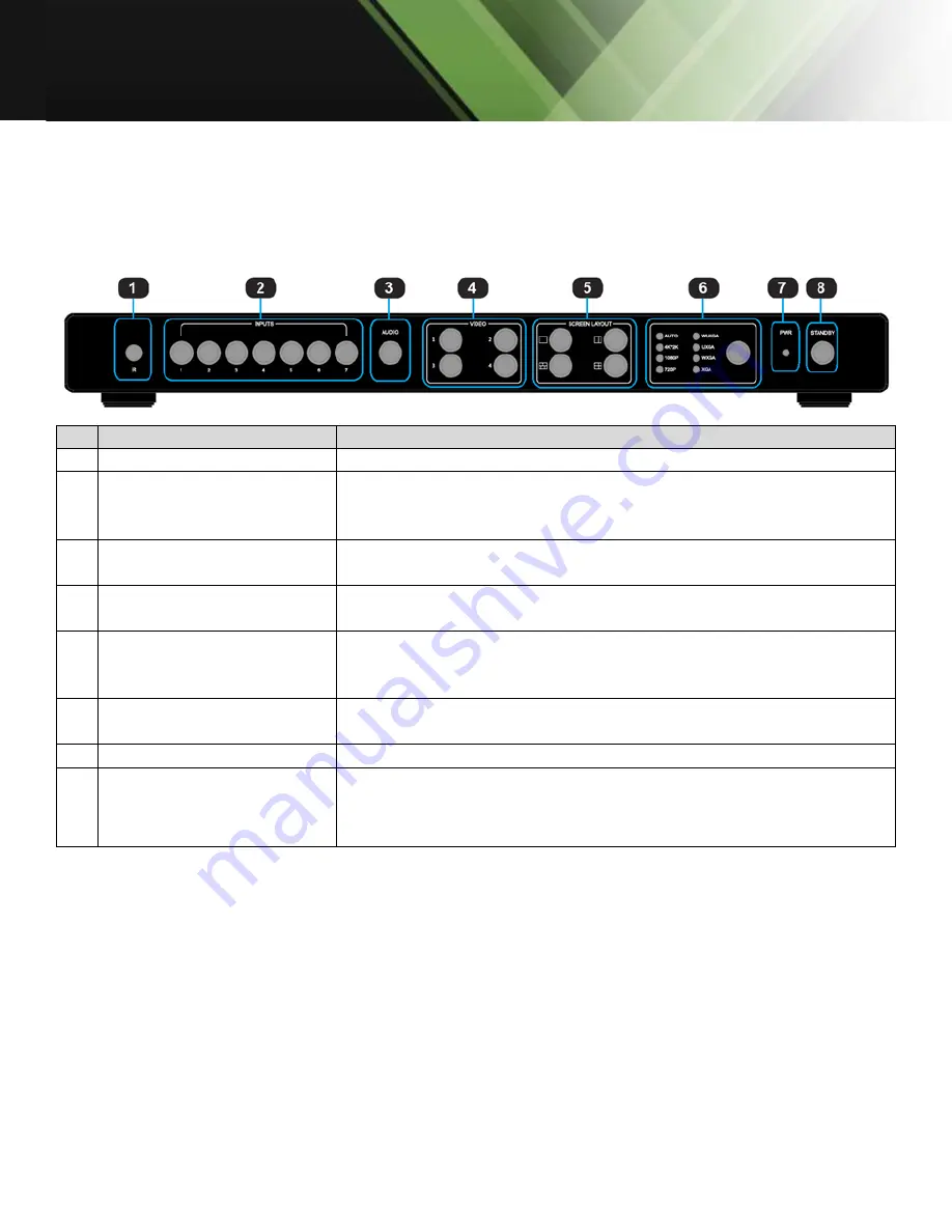
1.1 Panel Layout 

1.1.1 Front Panel 

ID  Name 

Description 

IR receive window 

IR receive sensor, receives the IR signals from the IR remote. 

Input Buttons and 
Indicator 

Press buttons 1-7 to select the corresponding video or audio 
input. The indicators mean the corresponding status of the video 
or audio input. 

Audio Selection Button 
and Indicator 

Press this button for the indicator to light up; this represents 
switching between audio outputs. 

Video Input Button and 
Indicator 

Press buttons 1-4 which indicates the selected corresponding 
windows. The indicates whether this window is active. 

Video Window Mode 
Button and Indicator 

Video window mode selection: single window, double windows, 
triple windows, and quadruple windows. The indicators mean 
whether this window is active. 

Output Resolution Button 
and Indicator 

Selects the related resolutions 

Power Indicator 

Indicates whether the power is working properly or not. 

Standby button and 
indicator 


Switches between standby and normal work modes. 


When this device is switched to the standby mode, the 
indicator lights up. 


Summary of Contents for MV71-4K

Page 1: ...www tekvox com MV71 4K 79064 User Manual MV71 4K 4K 7x1 Multiviewer Switcher All Rights Reserved Version 79064_2020V1 0...

Page 2: ...es of the trademark owner No part of this publication may be copied or reproduced without prior written consent FCC Statement This equipment generates uses and can radiate radio frequency energy and i...

Page 3: ...moisture or install this product near water Do not put any heavy items on the product s power cable Do not remove the housing of the device as opening or removing housing may expose you to dangerous...

Page 4: ...r 9 1 4 2 Wiring Diagram 10 2 Operation 10 2 1 Standby Mode Operational Mode 10 2 2 Screen Layout Configuration 11 2 2 1 Single Window 13 2 2 2 Double Windows 14 2 2 3 Triple Windows 15 2 2 4 Quadrupl...

Page 5: ...www tekvox com MV71 4K 79064 User Manual 3 3 2 EDID Management 29 3 4 Web Settings 34 3 4 1 General Settings 34 3 4 2 Advanced Settings 37 4 Firmware Update 40 5 Specifications 41...

Page 6: ...ts switching between audio outputs 4 Video Input Button and Indicator Press buttons 1 4 which indicates the selected corresponding windows The indicates whether this window is active 5 Video Window Mo...

Page 7: ...o an HD or 4K display 5 Analog audio input 1 7 7 channel stereo analog audio input Connect a 3 5mm mini stereo cable from the Line Out jack on the audio source to this jack 6 HDMI input 1 4 Connect up...

Page 8: ...deo input or audio input 3 Windows 1 4 Press 1 7 buttons to select the corresponding window for select video input 4 Screen Layout Select Single mode Double mode Triple mode or Quadruple mode 5 Audio...

Page 9: ...urces to the input ports DISPLAYPORT 5 DISPLAYPORT 6 Connect up to one Hi Def VGA or YPbPr sources to the input ports RGB YPbPr on the Multiviewer Switcher 2 Connect an 4K or HD display to the HDMI Ou...

Page 10: ...PWR LED next to the Power button on the front panel indicates the power state of the Multiviewer Switcher This indicator remains illuminated as long as power is being supplied to the Multiviewer Switc...

Page 11: ...the four modes above For example if you want to use the mode for quadruple windows press the button so that the icon is displayed or the button in the remote The button indicator on the panel will li...

Page 12: ...defined as an input However we want to define the operation in the single window to introduce the basic operation before introduction to the operation in multiple windows In the following example sev...

Page 13: ...gnal of DisplayPort5 Method 1 Press the INPUTS 5 button on the front panel or remote Method 2 Press the Video 1 button on the front panel or remote The 1 button indicator on the panel will turn solid...

Page 14: ...itch to Window 1 the signal of DisplayPort5 Method 1 Press the INPUTS 5 button on the front panel or remote The Video 1 and 2 button indicators will blink this indicates that the two buttons can be se...

Page 15: ...re made use the last configuration The windows are shown as follows 3 If you want to switch to Window 1 and the DisplayPort5 signal Method 1 Press the INPUTS 5 button on the front panel or remote The...

Page 16: ...is configured to HDMI3 input HDMI3 is the factory default If any changes are made use the last configuration Window 4 is configured to HDMI4 input HDMI4 is the factory default If any changes are made...

Page 17: ...icator indication Auto 4K 2K 3840 x 2160 30Hz 1080P 1920 x 1080 60Hz 720P 1280 x 720 60Hz WUXGA 1900 x 1200 60Hz UXGA 1600 x 1200 60HZ WXGA 1280 x 800 60Hz XGA 1024 x 768 60Hz Auto means that the outp...

Page 18: ...for audio switching Method 1 1 Press audio button The corresponding indicator will light up This means that the audio output is selected If the Input indicator of the corresponding audio source turns...

Page 19: ...If HDMI or DisplayPort input signals have audio format then the digital audio signal is used If these signals are without audio format then it will automatically switch to the 3 5mm analog input Audi...

Page 20: ...how when inputs or volume levels are changed These ODS images can be turned off using control commands Each window displays an input source the resolution of the input signal and whether or not there...

Page 21: ...www tekvox com MV71 4K 79064 User Manual Quadruple Windows Audio Mute Indicators Volume Adjustment VGA Auto Menu IP Address...

Page 22: ...RS232 Settings RS 232 port DB 9 Note Connect to RXD TXD and GND only RS 232 Settings Description Setting Baud Rate 9600 Data Bits 8 Parity None Stop Bits 1 Hardware Flow Control None Note For more inf...

Page 23: ...address and port number via the information from the OSD Whether MV71 is in single window mode or in multiple window mode IP address and port number can always be obtained from Window 1 When there is...

Page 24: ...Manual Make sure that the PC and MV71 are in the same network segment Click Search The following device list is shown Select the device and click Setup The IP information is obtained from the Device...

Page 25: ...ch to the triple windows Quadruple Windows ATM 09 SCR_LYT W 4 Switch to the quadruple windows 3 3 1 2 Video Input Selection Function Item Command Description Video Input Selection Viewer 1 ATM 0A VDO_...

Page 26: ...T W 3 p Viewer 4 ATM 0A WIN_RAT W 4 p 3 3 1 6 Resolution Selection Function Item Command Description HDMI Output Resolution Select resolution for HDMI video output ATM 09 OPT_TIM W p p Video Resolutio...

Page 27: ...ust the VGA Input ATM 08 VGA_AUT W When VGA Input is selected automatically adjust image position OSD Control Toggle Audio OSD ATM 09 AUD_OSD W x x Audio volume mute OSD setting 0 Audio OSD On 1 Audio...

Page 28: ...of HDMI Output ATM 08 HDO_HDP R Read Check the HDCP switch status of the HDMI output port Check HDMI Output Timing ATM 09 HDO_EDI W 1 Read Check the timing of the HDMI output port Check HDBaseT Output...

Page 29: ...mple EDID presets can be recalled or EDID data can be captured or loaded into ROM and copied to each input The simplest method is to use the built in preset EDIDs and assign them to an input Example A...

Page 30: ...0p 8 channel 4 EDID 4 1080p 2 channel Copy Preset EDID to Input Port 4 ATM 0B EDI_POR W 4 C x x Preset EDID Number 1 4 1 EDID 1 4Kx2K 30Hz 8 channel 2 EDID 2 4Kx2K 30Hz 2 channel 3 EDID 3 1080p 8 chan...

Page 31: ...3 EEPROM 3 4 EEPROM 4 5 EEPROM 5 6 EEPROM 6 7 EEPROM 7 Copy EEPROM EDID to Input Port 3 ATM 0B EDI_POR W 3 E x x EEPROM EDID Source 1 7 1 EEPROM 1 2 EEPROM 2 3 EEPROM 3 4 EEPROM 4 5 EEPROM 5 6 EEPROM...

Page 32: ...e 1 7 1 EEPROM 1 2 EEPROM 2 3 EEPROM 3 4 EEPROM 4 5 EEPROM 5 6 EEPROM 6 7 EEPROM 7 Write EDID Name EEPROM ATM 13 EDI_NAE W x 4K2K_8CH_x x Internal EDID No 1 7 1 EDID 1 2 EDID 2 3 EDID 3 4 EDID 4 5 EDI...

Page 33: ...M 09 EDI_POR R x x Input Port to Read 1 7 1 Input port 1 HDMI 1 2 Input port 2 HDMI 2 3 Input port 3 HDMI 3 4 Input port 4 HDMI 4 5 Input port 5 DisplayPort 1 6 Input port 6 DisplayPort 2 7 Input port...

Page 34: ...lowing the MV71 to be controlled For more information about how to obtain the IP address see 3 2 IP Settings For example the obtained IP address is 192 168 3 5 and port number is 23 Input http 10 0 0...

Page 35: ...ble screen layout and only W1 W2 and W3 in the Triple screen layout Press Submit to save changes 3 4 1 3 Aspect Ratio For each of the viewing windows W1 4 choose which aspect ratio to display the vide...

Page 36: ...User Manual 3 4 1 4 Audio Input Select which video source 1 7 to use as the audio source Press Submit to save changes 3 4 1 5 Audio Volume Set the volume to an integer value from 0 Mute 10 Max Volume...

Page 37: ...on AUTO based on display EDID 4Kx2K 30Hz 1920x1080 60Hz 1080p 1280x720 60Hz 720p 1920x1200 60Hz 1600x1200 60Hz 1280x800 60Hz 1024x768 60Hz Press Submit to save changes 3 4 2 Advanced Settings Power Sw...

Page 38: ...after an input is no longer detected before entering power saving mode Time can be any integer value from 0 Never enter power saving mode 60 minutes Recommended values include 5 10 15 30 and 60 minut...

Page 39: ...4 2 5 Auto Position Setting When this option is selected the VGA input s position clock and phase will be adjusted automatically If the Video OSD is enabled this setting will be indicated by Auto Adj...

Page 40: ...2 Connect the USB drive to the USB port on the rear of the device 3 Connect the HDMI display to the MV71 4 Turn on the MV71 The display device displays the HDMI output signal after normal boot of the...

Page 41: ...und 3 5mm mini jack 1 Optical Audio Supported Input Resolutions HDMI Up to 4Kx2K 30Hz DisplayPort Up to 4Kx2K 60Hz Output Resolutions 4Kx2K 1080p 720p WUXGA UXGA WXGA XGA Control Ports 1 RS 232 DB 9 F...

Reviews: