


Pulse Pro
fi
ling Application
part of a pulse. The pulse criteria de
fi
nes the edges of the positive portion of the
entire pulse and is relative (or added) to the measurement threshold if threshold is
enabled. It is relative to the noise
fl
oor if the measurement threshold is disabled.
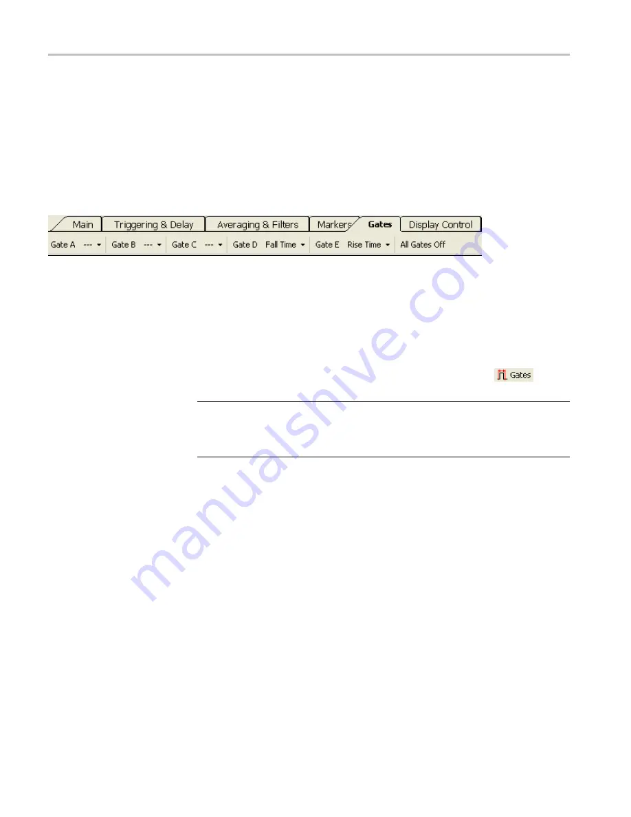
Gates
The time gates allow you to characterize the incoming signal. Rise time, fall time,
and droop measurements are very sensitive to the position of the gates. These
measurements use the position of the gates as starting and end points for the
measurement. (See page 42,
Gate Measurement Types in Gates Toolbar
Gates A through E.
There are
fi
ve time gate pairs (A-E). The drop down menu for
each gate allows you to set measurement type and gate position.
You can then select Set Position from the gate drop down menu to access the
Set
Position
window to place the gate. You can also place the gate by clicking in
the Panoramic Trace window.
To move or place a particular gate, the Pointer Control mode (found in the Display
Control toolbar and in the Results window) must be set to Gates (
).
NOTE.
Only one gate can be active at a time, though all
fi
ve gates can be
displayed simultaneously. The active gate will have an asterisk (*) next to its
letter in the toolbar and the gate letter will be underlined and appear slightly
larger in the trace display.
The following general gate positioning diagram shows where to place the gates
for the various measurement types. (See Figure 4.)
Gate Measurement Types
in Gates Toolbar
The time gates allow characterization of the pulse signal to include the following
parameters, selectable in the Gates toolbar from the Gate drop down menus. You
can also make all of the following measurements automatically by clicking the
Start Measurement
button in the Auto Measure window.
A brief description of every measurement follows. After the list of measurements,
there are some measurement examples that guide you through the gate setups.
Rise Time (RT).
Returns the time required for the signal to increase in amplitude
from 10% to 90% of the amplitude de
fi
ned by the placement if the right-most gate.
RT is measured on the
fi
rst complete pulse: the left gate determines the start of
data and the right gate marks the highest point to be considered.
42
RF and Microwave Power Sensors/Meters
Summary of Contents for PSM3000 Series
Page 2: ......
Page 6: ......
Page 10: ...Table of Contents iv RF and Microwave Power Sensors Meters...
Page 14: ...Preface viii RF and Microwave Power Sensors Meters...
Page 26: ...Getting Started 12 RF and Microwave Power Sensors Meters...
Page 32: ...Operating Basics 18 RF and Microwave Power Sensors Meters...
Page 74: ...High Speed Logger Application 60 RF and Microwave Power Sensors Meters...


