background image

Appendix C: P6316 General-Purpose Logic Probe Information

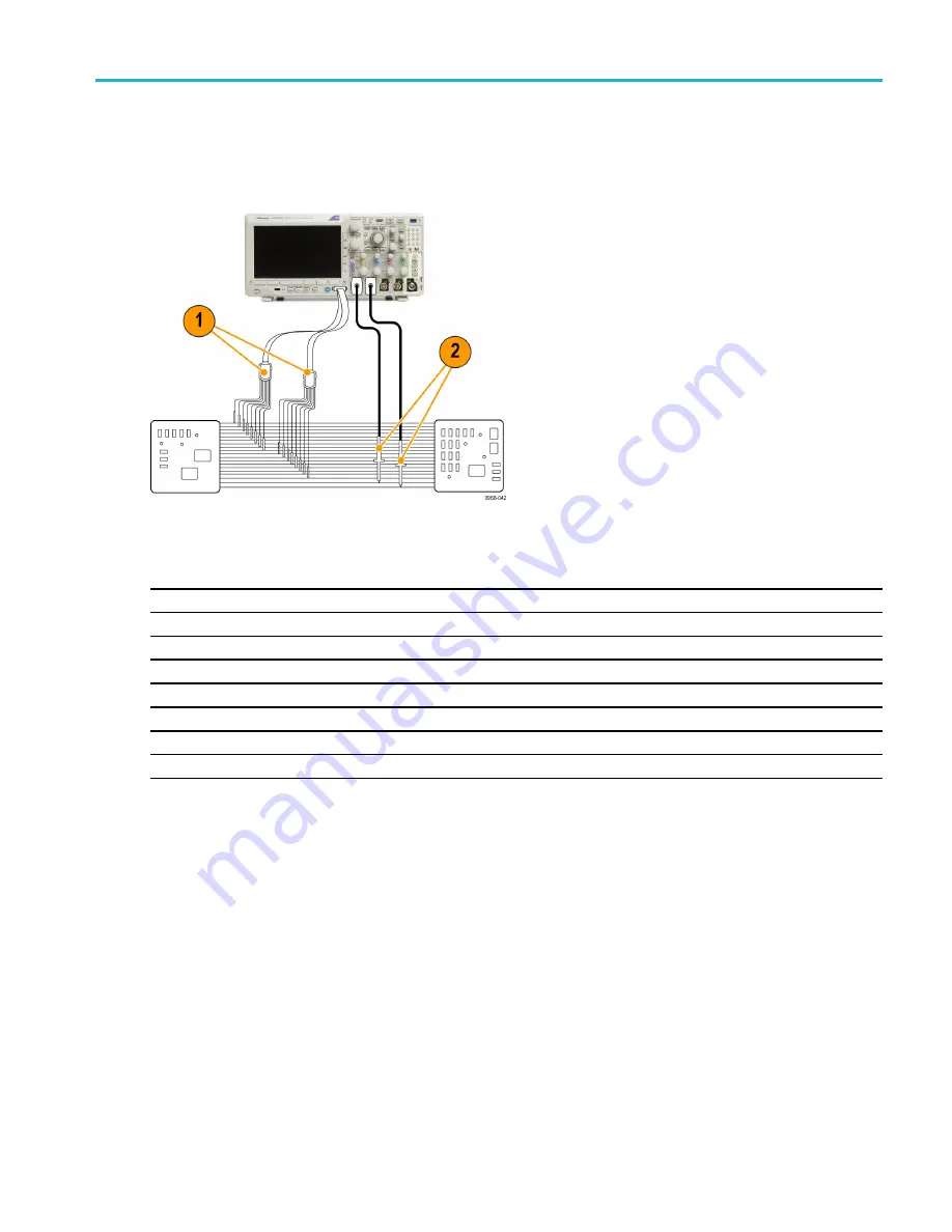
Typical Application

1.

Use the P6316 probe to view digital signals on a system bus.

2.

Use an analog probe, such as the TPP0250, TPP0500B or TPP1000 passive probe, to view analog waveform information.

Probe lead sets:

Probe

Group 1

Group 2

Black probe

0

8

Brown probe

1

9

Red probe

2

10

Orange probe

3

11

Yellow probe

4

12

Green probe

5

13

Blue probe

6

14

Violet probe

7

15

MDO3000 Series Oscilloscopes User Manual

207

Summary of Contents for MDO3012

Page 1: ...x MDO3000 Series Mixed Domain Oscilloscopes ZZZ User Manual P077096802 077 0968 02...

Page 2: ......

Page 3: ...MDO3000 Series Mixed Domain Oscilloscopes ZZZ User Manual xx www tek com 077 0968 02...

Page 4: ...TEKTRONIX and TEK are registered trademarks of Tektronix Inc e Scope iView OpenChoice and TekSecure and TekVPI are registered trademarks of Tektronix Inc MagniVu and Wave Inspector are trademarks of...

Page 5: ...is located Customer shall be responsible for paying all shipping charges duties taxes and any other charges for products returned to any other locations This warranty shall not apply to any defect fai...

Page 6: ...nter is located Customer shall be responsible for paying all shipping charges duties taxes and any other charges for products returned to any other locations This warranty shall not apply to any defec...

Page 7: ...ive Voltage Probe 11 Compensating a non TPP0250 non TPP0500B or non TPP1000 Passive Voltage Probe 13 Application Module Free Trial 14 Installing an Application Module 14 Upgrading Bandwidth 15 Changin...

Page 8: ...g a Waveform 108 Setting Input Parameters 109 Positioning and Labeling Bus Signals 113 Positioning Scaling and Grouping Digital Channels 113 Viewing Digital Channels 115 Annotating the Screen 115 View...

Page 9: ...TPP0250 TPP0500B and TPP1000 250 MHz 500 MHz and 1 GHz 10X Passive Probes Information 198 Operating Information 198 Connecting the Probe to the Oscilloscope 198 Compensating the Probe with MDO3000 Ser...

Page 10: ...Table of Contents iv MDO3000 Series Oscilloscopes User Manual...

Page 11: ...e exposed While using this product you may need to access other parts of a larger system Read the safety sections of the other component manuals for warnings and cautions related to operating the syst...

Page 12: ...ssories for mechanical damage and replace when damaged Do not use probes or test leads if they are damaged if there is exposed metal or if a wear indicator shows Examine the exterior of the product be...

Page 13: ...p or probe reference lead Connect and disconnect properly Connect the probe output to the measurement product before connecting the probe to the circuit under test Connect the probe reference lead to...

Page 14: ...t unless another person capable of rendering first aid and resuscitation is present Disconnect power To avoid electric shock switch off the product power and disconnect the power cord from the mains p...

Page 15: ...e product DANGER indicates an injury hazard immediately accessible as you read the marking WARNING indicates an injury hazard not immediately accessible as you read the marking CAUTION indicates a haz...

Page 16: ...t Tektronix UK Ltd Western Peninsula Western Road Bracknell RG12 1RF United Kingdom 1 This product is intended for use in nonresidential areas only Use in residential areas may cause electromagnetic i...

Page 17: ...1 Safety Requirements for Electrical Equipment for Measurement Control and Laboratory Use Part 1 General Requirements EN 61010 2 030 Safety Requirements for Electrical Equipment for Measurement Contro...

Page 18: ...ive pollution occurs Products in this category are generally encapsulated hermetically sealed or located in clean rooms Pollution degree 2 Normally only dry nonconductive pollution occurs Occasionally...

Page 19: ...wiring at utilization points socket outlets and similar points Category III In the building wiring and distribution system Category IV At the source of the electrical supply to the building NOTE Only...

Page 20: ...cled appropriately This symbol indicates that this product complies with the applicable European Union requirements according to Directives 2002 96 EC and 2006 66 EC on waste electrical and electronic...

Page 21: ...10 M Record Length 2 ch 10 M 10 M 10 M 10 M 10 M Record Length 4 ch 10 M N A 10 M N A 10 M RF Frequency Range 9 kHz 1 GHz 9 kHz 1 GHz 9 kHz 500 MHz 9 kHz 500 MHz 9 kHz 350 MHz AFG Outputs 1 1 1 1 1 M...

Page 22: ...rates of 2 5 GS s on all analog channels 5 GS s on 1 or 2 channels for the MDO3104 or MDO3102 10 M points record length on all channels Maximum waveform capture rate 280 000 waveforms second with Fast...

Page 23: ...ate documenting traceability to national metrology institute s and ISO9001 quality system registration French Option L1 335 3264 XX Italian Option L2 335 3265 XX German Option L3 335 3266 XX Spanish O...

Page 24: ...1 0346 XX Switzerland Option A5 161 0347 XX Japan Option A6 161 0342 XX China Option A10 161 0341 00 India Option A11 161 0349 XX Brazil Option A12 161 0356 XX Power Cord No power cord or AC adapter O...

Page 25: ...Add password protected security to enable or disable all communication ports and firmware upgrades to any MDO3000 Series oscilloscope Bandwidth upgrades Upgrade the analog bandwidth on MDO3000 Series...

Page 26: ...X Traditional Chinese 071 0976 XX Korean 071 0977 XX MDO3000 Series Oscilloscopes User Manual Russian 071 0978 XX MDO3000 Series Oscilloscopes Programmer Manual Describes commands for remote control o...

Page 27: ...ssification and Security Instructions Describes how to sanitize or remove memory devices from the Tektronix MDO3000 Series oscilloscopes 077 0980 XX The MDO3000 Series oscilloscopes support a multitud...

Page 28: ...operating input level Average Continuous Power 20 dBm 0 1 W DC maximum before damage 40 VDC Max No damage 33 dBm 2 W CW Peak Pulse Power 45 dBm 32 W Peak Pulse Power defined as 10 s pulse width 1 duty...

Page 29: ...damage to the surface of the oscilloscope or probes do not use any abrasive or chemical cleaning agents Connecting Probes The oscilloscope supports probes with the following 1 Tektronix Versatile Pro...

Page 30: ...her communication 5 Logic Probe Interface The P6316 probe provides 16 channels of digital on or off state information 6 The TPA N VPI Adapter allows you to use TekVPI probes in the RF input For more i...

Page 31: ...as any circuits that you are testing If you are working with static sensitive components ground yourself Static electricity that builds up on your body can damage static sensitive components Wearing a...

Page 32: ...2 If you want to remove power completely disconnect the power cord from the rear panel of the instrument Functional Check Perform this quick functional check to verify that your oscilloscope is operat...

Page 33: ...d service personnel Compensating a TPP0250 TPP0500B or TPP1000 Passive Voltage Probe The MDO3000 Series oscilloscopes can automatically compensate TPP0250 TPP0500B and TPP1000 probes This eliminates t...

Page 34: ...mp terminals 4 Push a front panel button for an input channel connected to the probe you wish to compensate 1 2 3 or 4 5 Notice on the lower menu that the oscilloscope has automatically set the probe...

Page 35: ...annel NOTE A factory calibration will delete all stored compensation values NOTE A probe compensation failure is most likely due to intermittent connection of the probe tip or ground connection during...

Page 36: ...r oscilloscope The trial period begins when you power on the oscilloscope for the first time After 30 days you must purchase the module if you want to continue using the application To see the date wh...

Page 37: ...ntil Modules is selected The licenses contained in the oscilloscope will be listed in the side menu Push the button next to the appropriate license to transfer You may transfer up to two licenses at o...

Page 38: ...MHz MDO3BW2T54 200 MHz 1 GHz MDO3BW2T104 350 MHz 500 MHz MDO3BW3T54 350 MHz 1 GHz MDO3BW3T104 500 MHz 1 GHz MDO3BW5T104 MDO3022 200 MHz 350 MHz MDO3BW2T32 200 MHz 500 MHz MDO3BW2T52 200 MHz 1 GHz MDO3...

Page 39: ...rmed in the field by the customer You will need to supply the model number and serial number when placing your order To determine the serial number of your instrument push Utility and then push About...

Page 40: ...key a message will be displayed indicating that you must power cycle the oscilloscope to enable the new features OK Accept 9 Power cycle the oscilloscope 10 To verify that the bandwidth has been upgr...

Page 41: ...language for the user interface Menus a English 6 Push USB Keyboard from the resulting side menu and turn Multipurpose a to select the desired language version of keyboard to use USB Keyboard English...

Page 42: ...Config Config 4 Push Set Date Time Utility Page Config Language Set Date Time About Manage Modules Options 5 Push the side menu buttons and turn both the Multipurpose a and Multipurpose b knobs to set...

Page 43: ...meeting warranted performance levels at those volts div settings Signal Path Compensation for Time and Frequency Domains To compensate the signal path 1 Warm up the oscilloscope for at least 20 minute...

Page 44: ...not include calibration to the probe tip See page 13 Compensating a non TPP0250 non TPP0500B or non TPP1000 Passive Voltage Probe Signal Path Compensation for Frequency Domain Only The signal path com...

Page 45: ...the software finder Download the latest firmware for your oscilloscope on your PC Unzip the files and copy the firmware img file into the root folder of a USB flash drive or USB hard drive 2 Power off...

Page 46: ...problem continues try a different model of USB flash or hard drive Finally if needed contact qualified service personnel NOTE Do not power off the oscilloscope or remove the USB drive until the oscil...

Page 47: ...select Config Config 10 Push About The oscilloscope displays the firmware version number Utility Page Config Language Set Date Time About Manage Modules Options 11 Confirm that the version number matc...

Page 48: ...he computer to the oscilloscope For VISA load the VISA drivers on your computer Also load your application such as OpenChoice Desktop You will find the drivers and OpenChoice Desktop software on the a...

Page 49: ...cable Cycle the power on the oscilloscope 3 Push Utility 4 Push Utility Page Utility Page 5 Turn Multipurpose a and select I O I O 6 If you are using USB the system sets itself up automatically for yo...

Page 50: ...formation below 8 If you want to change socket server parameters push Socket Server and enter new values through the resulting side menu 9 If you are using GPIB push GPIB Enter the GPIB address on the...

Page 51: ...ort for computer connectivity Use the rear and front panel USB 2 0 host port to connect your oscilloscope to USB flash drives Use the USB Device port to connect your oscilloscope to a PC or a PictBrid...

Page 52: ...indicator turns green for good status and red if the device detects a fault Ethernet LXI LAN Status 7 Push LAN Settings to display the network parameters configured on your oscilloscope LAN Settings 8...

Page 53: ...browser Change e Scope Password a Enabled more 2 of 2 14 Start your browser on your remote computer In the browser address line enter the host name a dot and the domain name together Alternatively jus...

Page 54: ...ides two way communication over an Internet Protocol based computer network You can use your oscilloscope s socket server feature to let your oscilloscope communicate with a remote terminal device or...

Page 55: ...ht Enabled Enabled Disabled 7 Choose whether the protocol should be None or Terminal A communication session run by a human at a keyboard typically uses a terminal protocol An automated session might...

Page 56: ...y typing in an open command with the oscilloscope s LAN address and port You can obtain the LAN address by pushing the Ethernet LXI lower menu button and the resulting LAN Settings side menu button to...

Page 57: ...board even if it is plugged in while the oscilloscope is powered on You can use the keyboard to quickly create names or labels You can bring up the Label button on the lower menu by pushing a Channel...

Page 58: ...ctions 1 Traditional oscilloscope front panel controls 2 10 digit keypad 3 Application module slots 4 Ground strap connector 5 Ground 6 PROBE COMP 7 Dedicated spectral analysis controls 8 Dedicated RF...

Page 59: ...to use NOTE The B1 and B2 buttons support up to two different serial or parallel buses 2 Push a lower menu button If a pop out menu appears turn Multipurpose a to select the desired choice If a pop u...

Page 60: ...off or on the ability to make smaller adjustments Using the Menu Buttons Use the menu buttons to perform many functions in the oscilloscope 1 Measure Push to perform automated measurements on waveform...

Page 61: ...ition Turn to adjust the vertical position of the corresponding waveform Push to center the waveform baseline indicator 12 Channel 1 2 3 or 4 Menu Push to set vertical parameters for input waveforms a...

Page 62: ...SPI buses MDO3COMP supports RS 232 RS 422 RS 485 and UART buses MDO3FLEX supports FlexRay buses MDO3USB supports USB 2 0 buses Also push the B1 or B2 button to display or remove the corresponding bus...

Page 63: ...or manual markers Using Other Controls 1 Cursors Push once to activate the two vertical cursors Push again to turn off all cursors Push and hold to bring up the cursor menu Use the menu to select the...

Page 64: ...a menu item Push Fine to make adjustments more slowly 6 Intensity Push to enable Multipurpose a to control waveform display intensity and knob b to control graticule intensity 7 Zoom button Push to a...

Page 65: ...ion 16 Autoset Push to automatically set the vertical horizontal and trigger controls for a usable stable display 17 Single Push to make a single sequence acquisition 18 Run Stop Push to start or stop...

Page 66: ...u 25 Save Recall Menu Push to save and recall setups waveforms and screen images to internal memory or a USB flash drive 26 Default Setup Push to perform an immediate restore of the oscilloscope to th...

Page 67: ...pped or between triggers You can change the horizontal or vertical position or scale to see approximately what the next acquisition will look like A B When using the average acquisition mode B shows t...

Page 68: ...shows time amplitude and delta values for each cursor For FFT measurements it shows frequency and magnitude For serial and parallel buses the readout shows the decoded values 8 The trigger level icon...

Page 69: ...gniVu appears in the readout 13 Measurement readouts show the selected measurements You can select up to four measurements to display at one time A symbol appears instead of the expected numerical mea...

Page 70: ...us indicator shows the bus number and bus type 19 For analog channels the waveform baseline indicator shows the zero volt level of a waveform assuming you have not used any offset The icon colors corr...

Page 71: ...Instrument 1 Vertical graticule labels 2 Start frequency 3 Reference level 4 Vertical scale 5 Center frequency 6 Span and resolution bandwidth 7 Stop frequency 8 Reference marker MDO3000 Series Oscil...

Page 72: ...in the Arbitrary Function Generator Display 1 If visible the output is on 2 AFG label 3 Waveform type e g Sine 4 Additive Noise icon 5 Frequency 6 Amplitude See page 185 Use the Arbitrary Function Ge...

Page 73: ...alue 4 Minimum measurement value recorded since you powered on the instrument or since you last pushed the Reset DVM Statistics menu item 5 Maximum measurement value recorded since you powered on the...

Page 74: ...be Interface 3 RF input connector 4 PROBE COMP Square wave signal source to compensate or calibrate probes Output voltage 0 2 5 V amplitude 1 behind 1 k 2 Frequency 1 kHz 5 Ground 6 Application Module...

Page 75: ...e port Use the USB 2 0 High Speed Device port to connect a PictBridge compatible printer or for direct PC control of the oscilloscope using USBTMC protocol NOTE The cable connected from the USB 2 0 De...

Page 76: ...rument to acquire signals using the analog channels 1 Connect the TPP0250 TPP0500B TPP1000 or VPI probe to the input signal source 2 Select the input channel by pushing the front panel buttons NOTE If...

Page 77: ...Tip Use the zoom feature to see multiple cycles of your signal in the upper part and a single cycle in the lower part of the display See page 149 Using Wave Inspector to Manage Long Record Length Wave...

Page 78: ...e label after you insert it if necessary 5 Push Insert Preset Label to add the label Insert Preset Label If you are using a USB keyboard use the arrow keys to position the insertion point and edit the...

Page 79: ...ttons to edit the label as needed Enter Character Back Space Delete Clear 9 Continue scrolling and pushing Select until you have entered all the desired characters For another label push the side and...

Page 80: ...connect the analog probe and then select the input channel See page 54 Setting Up Analog Channels To autoset a digital channel connect the logic probe and select the input channel See page 81 Setting...

Page 81: ...fore a signal can be displayed it must pass through the input channel where it is scaled and digitized Each channel has a dedicated input amplifier and digitizer Each channel produces a stream of digi...

Page 82: ...from the trigger point to the expansion point Adjust this by turning the Horizontal Position knob Use a positive time to acquire the record after the trigger point Use a negative time to acquire it b...

Page 83: ...ccurrence with hot colors like red yellow indicating frequently occurring events and colder colors like blue green indicating rarely occurring events Spectral uses color grading to indicate frequency...

Page 84: ...terpolated sampling Hi Res provides a higher resolution lower bandwidth waveform Envelope mode finds the highest and lowest record points over all acquisitions Envelope uses Peak Detect for each indiv...

Page 85: ...only work when the current sample rate is less than the maximum possible sample rate As soon as the oscilloscope starts to acquire at the maximum sample rate then the Peak Detect Hi Res and Sample mod...

Page 86: ...trigger event by a significant interval of time For example you can trigger on a sync pulse that occurs once every 10 ms and then look at high speed signal characteristics that occur 6 ms after the sy...

Page 87: ...o a file Print Send a pulse out the AUX OUT port Generate a remote interface SRQ Send an e mail notification Display a message on the oscilloscope display 1 Push Test 2 Push Application on the lower m...

Page 88: ...tions above you can now select Configure E mail from the side menu to define the parameters of the e mail Configure E mail NOTE There is a single set of SMTP server settings saved for both Act on Even...

Page 89: ...module ARINC429 and MIL STD 1553 MDO3AERO application module Parallel MDO3000 Series oscilloscope with the MDO3MSO option RS 232 RS 422 RS 485 and UART MDO3COMP application module USB 2 0 MDO3USB appl...

Page 90: ...el bus conditions refer to Triggering on Buses See page 95 Triggering on Buses To set up bus parameters 1 Push B1 or B2 to bring up the lower bus menu 2 Push Bus Turn Multipurpose a to scroll through...

Page 91: ...digital channel as the source for the bit Define Bits a Bit 15 b D15 4 Push Thresholds Bus B1 Parallel Define Inputs Thresholds B1 Label Parallel Bus Display Event Table You can set the threshold for...

Page 92: ...orms Hex Binary ASCII 7 Push Event Table and select On to display a list of bus packets with timestamps Event Table On Off Save Event Table For a clocked parallel bus the table lists the value of the...

Page 93: ...up or down on the screen See page 80 Event Table ARINC429 Bus To acquire data from an ARINC429 bus you need to setup these items 1 If you selected ARINC429 push Define Inputs and the appropriate side...

Page 94: ...ms 1 If you select I2C push Define Inputs and the appropriate side menu choices Bus B1 I2C Define Inputs Thresholds Include R W in Address No B1 Label I2C Bus Display Event Table You can assign the pr...

Page 95: ...ge of the signal to match the SPI bus being acquired SCLK 4 Set the level of the SS MOSI and MISO signals to match the SPI bus SS Active High Active Low Active High means that a signal is considered a...

Page 96: ...and select the number to match the bus Data Bits 7 8 4 Push Parity and turn Multipurpose a to match the polarity used by the bus as None Odd or Even Parity a None 5 Push Packets and select On or Off...

Page 97: ...a percentage of the position within the bit period or the unit interval Sample Point 50 For a CAN 2 0 bus the allowable sample point range is 5 to 95 For a CAN FD bus the allowable sample point range...

Page 98: ...it rate to a specific value To do so select Custom and then turn Multipurpose b to set the bit rate from 10 kbps to 1 Mbps When Standard is set to CAN FD this will be the SD bit rate 8 If Standard is...

Page 99: ...ing acquired Polarity Normal High 1 Polarity Inverted High 0 5 Push Configure and the appropriate side menu choices Bus B1 LIN Define Inputs Thresholds Configure B1 Label LIN Bus Display Event Table 6...

Page 100: ...re B1 Label RS 232 Bus Display Event Table 2 Push Type and turn Multipurpose a to select the type of audio bus data configuration on which to trigger Audio Bus Type 3 Select I2S to trigger on the stan...

Page 101: ...S USB MIL STD 1553 To acquire data from a MIL STD 1553 bus you need to also set up these items Bus B1 MIL 1553 Define Inputs Thresholds 800 mV 0 00 V RT 12 0 S 4 00 S B1 Label 1553 Bus Display Event T...

Page 102: ...he order of the bits and displays 0110 1000 If the bus display is set to hex the value displays as 68 If the bus display is set to ASCII the value displays as h Event Table In addition to seeing decod...

Page 103: ...nd You can connect a separate lead for each channel or a common ground lead for each group of 8 wires 3 If needed connect the appropriate grabber for each probe to the probe tip 4 Connect each probe t...

Page 104: ...in the group instead of individual channels 8 Push Thresholds on the lower menu You can assign a different threshold value to each channel 9 Push Edit Labels on the lower menu and create the label You...

Page 105: ...edges Using MagniVu you can see up to 16 times more detail than you can using normal digital channel sampling The MagniVu record is acquired in parallel to the main digital acquisition and is availabl...

Page 106: ...acquisition The serial bus features do not use data acquired in MagniVu mode Setting Up the RF Inputs Frequency and Span Parameters 1 The center frequency is a precise frequency at the center of the...

Page 107: ...urpose b knob or the keypad to enter the desired span If you use the keypad you can also use the resulting side menu choices to enter units Span b 3 00 GHz 4 Push Start to set the lowest frequency to...

Page 108: ...n requires a different unit of measurement than that being currently displayed Vertical Units dBm 5 Push Auto Level to direct the oscilloscope to automatically calculate and set the reference level fo...

Page 109: ...W and turn Multipurpose a to set the span RBW ratio This ratio is used when the RBW Mode is set to Auto The default is 1000 1 but you can set it to other values in a 1 2 5 sequence e g 1000 20000 5000...

Page 110: ...od slightly better than Hanning the spectral leakage is moderate and amplitude accuracy is fair Use the Hamming window for measuring sine periodic and narrow band random noise This window works well o...

Page 111: ...display Triggered display Trigger Modes The trigger mode determines how the instrument behaves in the absence of a trigger event Normal trigger mode enables the instrument to acquire a waveform only...

Page 112: ...remains disabled during the holdoff period that follows each acquisition Holdoffs Trigger Coupling Trigger coupling determines what part of the signal is passed to the trigger circuit Edge and Sequen...

Page 113: ...ou may uncover information that helps you find the source of the glitch Alternatively to see what is happening in your system as a result of the trigger event make the posttrigger period large enough...

Page 114: ...hout an application module Using the bus trigger on other buses requires use of a MDO3AERO MDO3AUDIO MDO3AUTO MDO3FLEX MDO3COMP MDO3EMBD or MDO3USB application module Bus 3 Turn Multipurpose a to sele...

Page 115: ...rm Events After the A Event occurs the trigger system looks for a specified number of B Events before triggering and displaying the waveform Pulse Width Trigger on pulses that are less than greater th...

Page 116: ...only digital channels Setup and Hold Trigger when a logic data input changes state inside of the setup or hold time relative to a clock edge Setup is the amount of time that data should be stable and...

Page 117: ...an MDO3FLEX module Audio requires an MDO3AUDIO module USB requires an MDO3USB module ARINC429 and MIL STD 1553 requires an MDO3AERO module Parallel requires option MDO3MSO See page 14 Application Mod...

Page 118: ...ue must be EQUAL and is locked to this value It is unlocked when the Trigger On conditions is changed If you have made a Trigger On selection of Data or Label and Data push Data on the lower menu and...

Page 119: ...of interest with the Multipurpose a and Multipurpose b knobs CAN and CAN FD Bus Trigger You can trigger on Start of Frame Type of Frame Identifier Data Id Data End of Frame Bit Suffing Error and Miss...

Page 120: ...ower menu to enter values for Message Error bit 9 Instr bit 10 Service Req bit 11 BCR bit 15 Busy bit 16 Subsystem Flag bit 17 DBCA bit 18 Terminal Flag bit 19 and Parity If you are setting up a MIL S...

Page 121: ...ill allow matching on up to 8 bytes of data All other qualifiers are limited to 4 bytes of specified data For LIN triggering occurs when the user selected data input matches the data and qualifier in...

Page 122: ...the trigger system looks for the B Event before triggering and displaying the waveform A and B triggers can and typically do have separate sources NOTE You can select sequence triggering when you cho...

Page 123: ...after the trigger delay time Trigger on B Events The A trigger arms the instrument Posttrigger acquisition starts on the nth B event Quick Tips B trigger delay time and horizontal position are indepe...

Page 124: ...g or digital waveforms are active then pressing Run Stop to stop acquisitions will cause the oscilloscope to wait for one more trigger event before stopping Once the acquisition occurs the Run Stop bu...

Page 125: ...the display push the corresponding front panel channel button or the D15 D0 button You can use the channel as a trigger source whether or not it is displayed Setting the Display Style and Persistence...

Page 126: ...XY Display Then push Triggered XY from the side menu A data point from the first waveform specifies the horizontal location while the corresponding data point from the second waveform specifies the ve...

Page 127: ...yle push Utility 2 Push Utility Page Utility Page 3 Turn Multipurpose a and select Display Display 4 Push Graticule on the lower menu Utility Page Display Backlight Intensity High Graticule Full Scree...

Page 128: ...ger type to video and set the vertical scale to 114 mV division The 114 mV division selection is available in the fine vertical scale settings for the channel when you set the trigger type to video Th...

Page 129: ...ay help prolong the LCD life Auto Dim On Off Time 60min Setting Waveform Intensity 1 Push Intensity on the front panel This will bring up the intensity readout on the display 2 Turn Multipurpose a to...

Page 130: ...al Position knob and Delay is set to On the horizontal position is set to 0 seconds If you push it and Delay is set to Off the horizontal position is set to 10 Original waveform Scaled horizontally Po...

Page 131: ...ton 1 2 3 or 4 to bring up the vertical menu for the designated waveform The vertical menu only affects the selected waveform Pushing a channel button will also select or cancel that waveform selectio...

Page 132: ...pes do not include a 250 MHz option on the menu 6 Push Label to create a label for the channel See page 55 Labeling Channels and Buses 7 Push More to access a pop up menu of additional features These...

Page 133: ...or set Measure Current to Yes Push A V ratio on the side menu and turn Multipurpose a to set the Amps Volts or Volts Amp ratio of your setup For example if you are measuring the drop across a 2 resist...

Page 134: ...TekVPI interface the oscilloscope sets the channel sensitivity coupling and termination resistance automatically to match the probe requirements Tek Probe II probes require use of the TPA BNC Adapter...

Page 135: ...nt panel bus button to select that bus 2 Turn the Multipurpose a knob to adjust the vertical position of the selected bus Labeling bus signals To label a bus do the following steps 1 Push the appropri...

Page 136: ...ou stop rotating the knob 6 To change the scale height of the digital channels push Height on the lower menu NOTE The S Small selection will display each waveform at 0 2 divisions tall The M Medium se...

Page 137: ...in green Logic low levels are displayed in blue When a single transition occurs during the time represented by one pixel column the transition edge is displayed in gray When multiple transitions occur...

Page 138: ...ultipurpose a knob to scroll through the list of letters numbers and other characters to select each desired character Alternatively use a USB keyboard to type in characters See page 35 Connecting a U...

Page 139: ...o bring up the frequency domain menu 2 Push Spectrum Traces to bring up the side menu of four different spectrum trace types that the MDO3000 can display Spectrum Traces Spectro gram Off Spectrum Free...

Page 140: ...old to On to display the max hold trace Max Hold On Off 5 Set Min Hold to On to display the min hold trace Min Hold On Off The figure to the right illustrates the different trace types 1 Normal trace...

Page 141: ...es that the minimum trace is currently selected Detection Types The MDO3000 calculates FFTs with a 1 000 to 2 000 000 point output depending on the acquisition settings It then reduces that FFT output...

Page 142: ...ude and the hotter colors of yellow and red indicating higher amplitude Each new acquisition adds another slice at the bottom of the spectrogram and the history moves up one row When acquisitions are...

Page 143: ...ified number of Peak Markers identified in this control then only the specified number of highest amplitude peaks will be marked Peak Markers a 5 On Off 3 Push To Center to set the center frequency to...

Page 144: ...of the obvious peaks in the display The Reference Marker is the highest peak It is marked with the red R in a triangle and its readout is shown in red text 1 Reference marker 2 Automatic markers Use T...

Page 145: ...ipurpose a knob and can be moved to any location you desire This enables easy measurement of any part of the spectrum as well as delta measurements to any part of the spectrum This also lets you measu...

Page 146: ...rement turn Multipurpose a to select the specific measurement and push OK Remove Measurement on the side menu Quick Tips To remove all measurements select Remove All Measurements A symbol appears inst...

Page 147: ...final value Delay The time between the mid reference default 50 amplitude point of two different waveforms See also Phase Phase The amount of time that one waveform leads or lags another waveform exp...

Page 148: ...am method uses the most common value found above the midpoint This value is measured over the entire waveform or gated region Low This value is used as 0 whenever high reference mid reference or low r...

Page 149: ...below the mid reference crossing in the waveform or gated region Rising Edge Count The number of positive transitions from the low reference value to the high reference value in the waveform or gated...

Page 150: ...grams Histogram Min Displays the voltage of the lowest nonzero bin in vertical histograms or the time of the left most nonzero bin in horizontal histograms Histogram Mean Measures the average of all h...

Page 151: ...ion the gates using the side menu options Gating Off Full Record Screen Between Cursors Statistics Statistics characterize the stability of measurements To adjust statistics 1 Push Measure 2 Push More...

Page 152: ...n Off Mean Std Dev Samples a 32 Reset Statistics Snapshot To see all the single sourced measurements at one moment in time 1 Push Measure 2 Push Add Measurement Add Mea surement Remove Measure ment In...

Page 153: ...ow Min Pk Pk CycleMean CycleRMS CycleArea Edges Pulses 3 203 kHz 208 5 s 1 144 s 14 286 66 77 7 143 7 600 V 8 800 V 19 20 V 5 396 V 8 206 V 654 6 Vs 0 2 Reference Levels Reference levels determine how...

Page 154: ...eference primarily for measurements between edges such as pulse widths Mid Ref 50 0 50 0 Low Ref 10 0 Set to Defaults Taking Automatic Measurements in the Frequency Domain To take an automatic measure...

Page 155: ...help will appear to explain the purpose of that measurement A Configure item will appear on the lower menu After you press Configure and set the measurement parameters in the resulting side menu the...

Page 156: ...he finished results Taking Manual Measurements with Cursors Cursors are on screen markers that you position in the waveform display to take manual measurements on acquired data They appear as horizont...

Page 157: ...cursors 3 Push Fine to toggle between a coarse and a fine adjustment for the Multipurpose a and Multipurpose b knobs Pushing Fine also changes the sensitivity of other knobs as well 4 Push and hold Cu...

Page 158: ...on the screen by pushing one or more of the channel 1 through 4 buttons or by pushing the D15 D0 button 10 Push and hold Cursors to display the cursor menu again 11 Push Source on the lower menu A pop...

Page 159: ...s selected the readout shows the decoded bus data in the format you have selected from the choices in the bus menu When a digital channel is selected the cursors show the values of all displayed digit...

Page 160: ...cursors in the upper graticule YT Setting Up a Histogram You can display a vertical voltage or horizontal time histogram Use histogram measurements to get statistical measurement data for a section of...

Page 161: ...the L left and R right boundaries of the histogram box Horiz Limits L a 584ns R b 760ns 7 Push Vert Limits on the side menu and turn the Multipurpose a and Multipurpose b to set the T top and B botto...

Page 162: ...readout list OK Add Mea surement To Reset Histogram Measurements and Statistics To reset the histogram measurements and statistics follow these steps 1 Push Waveform Histograms on the lower menu Add M...

Page 163: ...Waveforms Create math waveforms to support the analysis of your channel and reference waveforms By combining and transforming source waveforms and other data into math waveforms you can derive the da...

Page 164: ...rizontal scale and position from the sources in their math expressions Adjusting these controls for the source waveforms also adjusts the math waveform You can zoom in on math waveforms using the inne...

Page 165: ...r channel models FFT Source 1 4 Push Vertical Scale on the side menu repeatedly to select either Linear RMS or dBV RMS Vertical Units Linear RMS 5 Push Window on the side menu repeatedly to select the...

Page 166: ...the best window Description Window Rectangular The frequency resolution when using the Rectangular a k a boxcar or none window is very good the spectral leakage is high and amplitude accuracy is poor...

Page 167: ...Harris window is poor the spectral leakage is very low and amplitude accuracy is good Use the Blackman Harris window for measuring predominantly single frequency waveforms to look for higher order ha...

Page 168: ...Push Enter Selection 4 Turn Multipurpose a to select channel 1 5 Push Enter Selection 6 Turn Multipurpose a to select 7 Push OK Accept Using Spectrum Math The spectrum math feature lets you create a m...

Page 169: ...ly complete the calculation if the units of measure of the source waveforms when combined make logical sense Using Reference Waveforms and Traces Create and store a reference waveform or trace For exa...

Page 170: ...forms You can display all the reference waveforms at the same time Push the appropriate screen button to select a particular reference waveform Removing Reference Waveforms from the Display To remove...

Page 171: ...rn the Zoom knob To scroll through a zoomed waveform turn the Pan knob The Pan Zoom Control consists of 1 An outer pan knob 2 An inner zoom knob Zooming a Waveform To use zoom 1 Rotate the inner knob...

Page 172: ...ugh the waveform To use pan 1 Rotate the pan outer knob of the pan zoom controls to pan the waveform Turn the knob clockwise to pan forward Turn it counterclockwise to pan backwards The further you tu...

Page 173: ...he waveform automatically if they meet some special criteria or you can manually mark each item of interest You can use arrow keys to jump from mark to mark area of interest to area of interest You ca...

Page 174: ...ned mark push Set Clear It works on both manually and automatically created marks To automatically set and clear delete search marks 1 Push Search 2 Select the search type desired from the lower menu...

Page 175: ...cludes the following search capabilities Search Description Edge Searches for edges rising falling or both with a user specified threshold level Pulse Width Searches for positive or negative pulse wid...

Page 176: ...abel Data Label and Data Word End or Error 1 FD BRS Bit FD ESI Bit Form Error and Any Error are available only when CAN FD is selected as BUS Auto magnify As you adjust the horizontal scale control to...

Page 177: ...show whether the input signal is within the user defined vertical and horizontal bounds of the mask You can create your own mask or recall a mask from a file To set up and run a limit or mask test do...

Page 178: ...l Limit 200mdiv 10 Push Vertical Limit to set the mask vertical limits The units are referenced to graticule divisions where one major division contains 1 000 millidivisions mdov Vertical Limit 200mdi...

Page 179: ...E 9 800 0000E 3 7 2750E 9 900 0000E 3 2 8720E 9 800 0000E 3 1 1286E 9 500 0000E 3 1 1286E 9 200 0000E 3 7 5000E 9 100 0000E 3 MASK USER SEG3 POINTS 0 0E 0 0 0E 0 MASK USER SEG4 POINTS 0 0E 0 0 0E 0 MA...

Page 180: ...starting a test Repeat Test Set On for the test to repeat when it has run the minimum number of waveforms or the minimum amount of time Set Off tor the test to run a single time and not repeat Mask P...

Page 181: ...kly reload the settings to correctly display the test source for limit testing Have the mask automatically re scale with the source channel setting changes by selecting Set Up Mask on the lower menu a...

Page 182: ...or See an actual video picture See a video of a video of a video signal by connecting a cable from the VIDEO OUT in the rear panel to an analog input channel in the front panel Making Automated Power...

Page 183: ...menu buttons to select the desired analysis function Choose among Power quality Switching loss Harmonics Ripple Modulation Safe operating area Deskew See the MDO3PWR DPO3PWR and DPO4PWR Power Analysi...

Page 184: ...s Turn the Multipurpose a knob to scroll through the list of files Push Select on the front panel to open and close folders Naming your file The oscilloscope gives all files it creates a default name...

Page 185: ...ile that file is named tek00000 The next time you save the same type of file the file will be named tek00001 Editing file directory reference waveform or instrument setup names Give files descriptive...

Page 186: ...e Saving a Screen Image A screen image consists of a graphical image of the oscilloscope screen This is different from waveform data which consists of numeric values for each point in the waveform To...

Page 187: ...ard Copy See page 172 Printing a Hard Copy Saving and Recalling Waveform and Trace Data Waveform and trace data consists of the numeric values for each point in the waveform or trace It copies the dat...

Page 188: ...lay data or as baseband I and Q data TIQ files Use the I and Q data with Tektronix SignalVu Vector Signal Analysis software 4 Turn the Multipurpose b knob and select the location to save the waveform...

Page 189: ...d file Use this format if you intend to recall an analog waveform or RF trace to reference memory for viewing or measuring Spreadsheet file format csv Sets the oscilloscope to save data as a comma sep...

Page 190: ...can be displayed again with another push of the button NOTE 10 M reference waveforms are volatile and not saved when the oscilloscope power is turned off To keep these waveforms save them to external...

Page 191: ...tton To save setup information to a USB or network drive push the To File button To Setup 1 To Setup 2 more 4 If you are saving information to a USB or network drive turn Multipurpose a to scroll thro...

Page 192: ...flash drive then each push of the Save button will save current waveform data to the defined USB flash drive 1 To define the Save button behavior push Save Recall Menu 2 Push Assign Save to Save Scree...

Page 193: ...hlighted drive directory or file Format a highlighted drive Mounting a Network Drive Mount a network storage device such as a PC or a file server to save setups waveforms and screen images directly to...

Page 194: ...haring is enabled for the network location 4 Push OK Accept NOTE To unmount a network drive push Save Recall Menu on the front panel push File Utilities on the lower menu push more 1 of 2 on the side...

Page 195: ...n PictBridge Printer Settings Turn Multipurpose a to scroll through the list of available printers Push Select to choose the desired printer To add a non PictBridge USB printer to the list plug the pr...

Page 196: ...Saver off Printing to a PictBridge Printer To set up the oscilloscope to print to a PictBridge printer 1 Push Utility 2 Push Utility Page Utility Page 3 Turn Multipurpose a and select I O I O 4 Push U...

Page 197: ...ge Printer Disabled Off bus Printing Over Ethernet To set up the oscilloscope to print over Ethernet 1 Connect an Ethernet cable to the rear panel Ethernet port 2 Push Utility 3 Push Utility Page Util...

Page 198: ...you want to enter If you are using a USB keyboard use the arrow keys to position the insertion point and type in the printer name See page 35 Connecting a USB Keyboard to Your Oscilloscope ABCDEFGHIJ...

Page 199: ...ld OK Accept 13 Turn Multipurpose a and push Select or Enter Character as often as needed to enter the name 14 When done push OK Accept NOTE If you have multiple printers connected to the oscilloscope...

Page 200: ...etup Print Setup 5 Push Select Printer Utility Page Print Setup Select Printer N A Orientation Landscape Ink Saver Off PictBridge Printer Settings 6 Push Add E Mail Printer Select Printer Add Network...

Page 201: ...modified in the other location ABCDEFGHIJKLMNOPQRSTUVWXYZ abcdefghijklmnopqrstuvwxyz 0123456789_ 8 Push Select or Enter Character to let the oscilloscope know that you have picked the proper character...

Page 202: ...he TekSecure function If you have acquired confidential data on your oscilloscope you may want to execute the TekSecure function before you return the oscilloscope to general use The TekSecure functio...

Page 203: ...rity TekSecure Erase Memory 5 Push OK Erase Setup and Ref Memory on the side menu This erases data in the oscilloscope s reference waveform and setup memory locations OK Erase Setup Ref Memory To canc...

Page 204: ...then power it back on to complete the process To use TekSecure with the MDO3SEC application module installed 1 Push Utility 2 Push Utility Page Utility Page 3 Turn the Multipurpose a knob and select S...

Page 205: ...Erase Setup Ref Memory 6 Push Security Password Use Multipurpose a and the bottom menu to enter a password 7 Push Firmware Upgrades Read the on screen warnings To disable the ability to load new firmw...

Page 206: ...Save and Recall Information 9 Power off the oscilloscope and then power it back on to complete the process 184 MDO3000 Series Oscilloscopes User Manual...

Page 207: ...eet file stored externally or a predefined template You can modify your arbitrary waveform via an on screen editor and then replicate it out of the generator For more involved waveform manipulation yo...

Page 208: ...menu to set the frequency period amplitude offset and the high and low levels of the desired waveform 4 Push the Output Settings button on the lower menu to adjust the load impedance and amount of add...

Page 209: ...stored externally or a predefined template square sine ramp pulse or noise 1 Push the AFG button to bring up the AFG lower menu 2 On the lower menu push Waveform and turn Multipurpose a to select Arb...

Page 210: ...view of the overview as defined by the box in the top part of the screen This lower part shows up to 500 points of the record Turn the Multipurpose a knob to select a point to edit Turn the Multipurp...

Page 211: ...enu Off twice Be sure that you have a BNC cable connected from the AUX OUT port on the back to the channel 1 port on the front View your arbitrary waveform on the oscilloscope display 8 On the lower m...

Page 212: ...rbitrary waveform You cannot save them to files or recall them directly to the arbitrary waveform memory locations NOTE Loading from digital waveform sources will use the main waveform record MagniVu...

Page 213: ...use of analytical tools such as digital views of the signal bus views packet decoding search tools and packet decode tables with time stamp information Signal Inputs Any Ch1 Ch4 and with option MDO3M...

Page 214: ...les use of analytical tools such as digital views of the signal bus views packet decoding search tools and packet decode tables with time stamp information for low speed full speed and high speed USB...

Page 215: ...erminated 0 3 div at 1 mV div with the input DC 1 M coupled and 50 terminated All above specifications are increased by 0 01 divisions C above 40 C DC Gain accuracy 2 5 for 1 mV div derated at 0 100 C...

Page 216: ...racteristic Limits Vout HI 2 25 V open circuit 0 9 V into a 50 load to ground Auxiliary output AUX OUT Vout LO 0 7 V into a load of 4 mA 0 25 V into a 50 load to ground Instrument bandwidth includes i...

Page 217: ...oughout a single shot measurement The second term is due to both the absolute center frequency accuracy and the center frequency stability of the timebase and varies between multiple single shot measu...

Page 218: ...h auto settings on and signals 10 dB below reference level 2nd order intermodulation distortion 9 kHz to 15 MHz 55 dBc 2nd order intermodulation distortion 9 kHz to 15 MHz 60 dBc typical With auto set...

Page 219: ...kHz typical For AC measurements the input channel vertical settings must allow the Vpp input signal to cover between 4 and 8 divisions Frequency Accuracy 10 ppm Frequency Counter Maximum Input Frequen...

Page 220: ...hown in the illustrations below Compensating the Probe with MDO3000 Series Oscilloscopes For information on compensating the probe refer to the related section earlier in this manual See page 11 Compe...

Page 221: ...er Tektronix part number 013 0362 xx Micro hook tip Use this tip to access test points in tight spaces Press the hook tip onto the probe tip and then extend the pincers around the circuit Rating 300 V...

Page 222: ...Optional Accessories The accessories shown below are available for the probes and are rated 30 V unless indicated otherwise Accessory Part number MicroCKT Test Tip One ships with each oscilloscopes 2...

Page 223: ...echanical specifications Characteristic TPP0250 TPP0500B TPP1000 Bandwidth 3 dB 250 MHz 500 MHz 1 GHz System rise time typical 1 4 ns 700 ps 450 ps System input capacitance Rigid tip 3 9 pF 0 3 pF Pog...

Page 224: ...nces Characteristics Description EC Declaration of Conformity Compliance was demonstrated to the following specification as listed in the Official Journal of the European Communities Low Voltage Direc...

Page 225: ...the measurement instrument Avoid Electric Shock To avoid injury or loss of life do not connect or disconnect probes or test leads while they are connected to a voltage source Observe All Terminal Rati...

Page 226: ...Hz 10X Passive Probes Information CAUTION Caution statements identify conditions or practices that could result in damage to this product or other property Symbols on the Product These symbols may app...

Page 227: ...des eight signals on one row and eight grounds along the opposite row The P6316 is included with option MDO3MSO A pair of interchangable flying lead sets are included with the probe The lead sets brin...

Page 228: ...all 16 channels Channel label To set and view bus characteristics do the following Push the B1 to B2 buttons The setup screens allow you to set and view various bus characteristics For buses such as S...

Page 229: ...bus 2 Use an analog probe such as the TPP0250 TPP0500B or TPP1000 passive probe to view analog waveform information Probe lead sets Probe Group 1 Group 2 Black probe 0 8 Brown probe 1 9 Red probe 2 1...

Page 230: ...Part number 1 8 channel leadset 2 196 3508 XX 2 Micro grabber clip 2 kits of 10 each 020 2896 XX 3 Probe tip 2 kits of 5 each 020 2897 XX Instructions English Japanese Simplified Chinese languages 1 e...

Page 231: ...2 F non condensing Altitude Operating 3 000 meters 9 843 feet Non operating 12 000 meters 39 370 feet Equipment Recycling This product complies with the European Union s requirements according to Dire...

Page 232: ...y qualified service personnel Do Not Operate in Wet Damp Conditions Do Not Operate in an Explosive Atmosphere Keep Product Surfaces Clean and Dry Safety Terms and Symbols in This Manual These terms ma...

Page 233: ...eatures or use of this software must display the following acknowledgment This product includes software developed by the OpenSSL Project for use in the OpenSSL Toolkit http www openssl org 4 The name...

Page 234: ...vered by the same copyright terms except that the holder is Tim Hudson tjh cryptsoft com Copyright remains Eric Young s and as such any Copyright notices in the code are not to be removed If this pack...

Page 235: ...FOR ANY DIRECT INDIRECT INCIDENTAL SPECIAL EXEMPLARY OR CONSEQUENTIAL DAMAGES INCLUDING BUT NOT LIMITED TO PROCUREMENT OF SUBSTITUTE GOODS OR SERVICES LOSS OF USE DATA OR PROFITS OR BUSINESS INTERRUPT...

Page 236: ...Appendix D OpenSSL License 214 MDO3000 Series Oscilloscopes User Manual...

Page 237: ...er 101 B W button 41 B1 B2 67 68 95 Backlight intensity 106 Bandwidth xvi 110 resolution 86 Baseline indicator 86 Baseline indicators 47 Before Installation 1 Blackman Harris FFT window 88 145 Blue li...

Page 238: ...Delete directory or file 171 Depth MDO3000 5 Deskew 111 Detection types 119 Digital channels 115 Baseline indicators 47 Group icon 48 scaling positioning grouping and labeling 113 setup 81 Digital Vo...

Page 239: ...TPP0250 non TPP0500B or non TPP1000 voltage probe 13 compensate the signal path 21 connect probes and adapters 7 connect to a computer 26 erase memory 180 label channels and buses 55 manage long reco...

Page 240: ...MDO3AUDIO 3 67 191 MDO3AUTO 3 67 191 MDO3COMP 3 67 191 MDO3EMBD 3 67 191 MDO3FLEX 67 191 MDO3LMT 3 155 191 MDO3PWR 3 67 160 192 MDO3USB 3 67 192 Mean measurement 127 128 Measure button 38 124 129 130...

Page 241: ...89 91 Pouch probe and accessory 2 Power cord 2 input 53 off 10 removing 10 supply 9 switch 44 Power measurements 160 Predefined math expressions 141 Pretrigger 89 91 Previous button 42 Print 173 E mai...

Page 242: ...ide panel connector 52 Sigma1 measurement 128 Sigma2 measurement 128 Sigma3 measurement 128 Signal path compensation 21 Frequency domain 22 Time and frequency domains 21 Single button 43 102 Single se...

Page 243: ...7 95 162 172 bus trigger 98 Device port 53 flash drive 29 host ports 44 User interface language 18 User marks 151 Utility button 18 20 21 39 105 106 115 116 173 Utility menu 19 20 39 44 105 116 117 V...

Reviews: