


Circuit Description—Type 324
and from the 5 to 2 yS positions, thus increasing the
AU TO repetition rate of the multivibrator. Changing the
AUTO repetition rate keeps the sweep intensity relatively
constant despite changes in sweep rate.
SWEEP GENERATOR < £ >
General
The Sweep Generator provides a linear sawtooth voltage
to the Horizontal Amplifier. It also controls the minimum
time between sweeps and provides unblanking to the
cathode-ray tube electron beam during sweep time. When
E X T H O R IZ operation is selected, the Sweep Generator
stops generating sweep voltages and provides continuous
unblanking to the cathode-ray tube. The unblanked state
can be interrupted by application of an external blanking
signal.
Block Diagram Description
Refer to the block diagram on the Sweep Generator
schematic diagram page. Triggers from the Trigger Gener
ator are received through C301 and applied to the Sweep
Gate circuit, which then develops a negative gate. As a
result, the Disconnect Diode stops conducting. This allows
the Miller Circuit to create a linear sawtooth voltage which
is sent to the Horizontal Amplifier. When the sawtooth has
sufficient amplitude to provide full horizontal trace deflec
tion, feedback current through the SWEEP LENGTH
potentiometer is sufficient to reset the Sweep Gate circuit.
The disconnect diode then conducts and the sweep voltage
rapidly decreases to its initial value, causing retrace to
occur.
The sweep must start at the same quiescent DC voltage
level for each sweep, or horizontal jitter will appear. The
same signal that causes retrace is therefore sent to the Hold-
off Circuit to block triggers from the Sweep Gate until the
sweep circuitry has stabilized. The holdoff time is con
trolled by capacitors which are selected by the various
positions of the T IM E /D IV switch.
operation can be understood by simply comparing a triode
vacuum tube to it, with the cathode, grid, and plate com
paring to the source, gate, and drain respectively. Like the
vacuum tube, the FET has high input impedance and only
leakage current flows in the gate circuit.
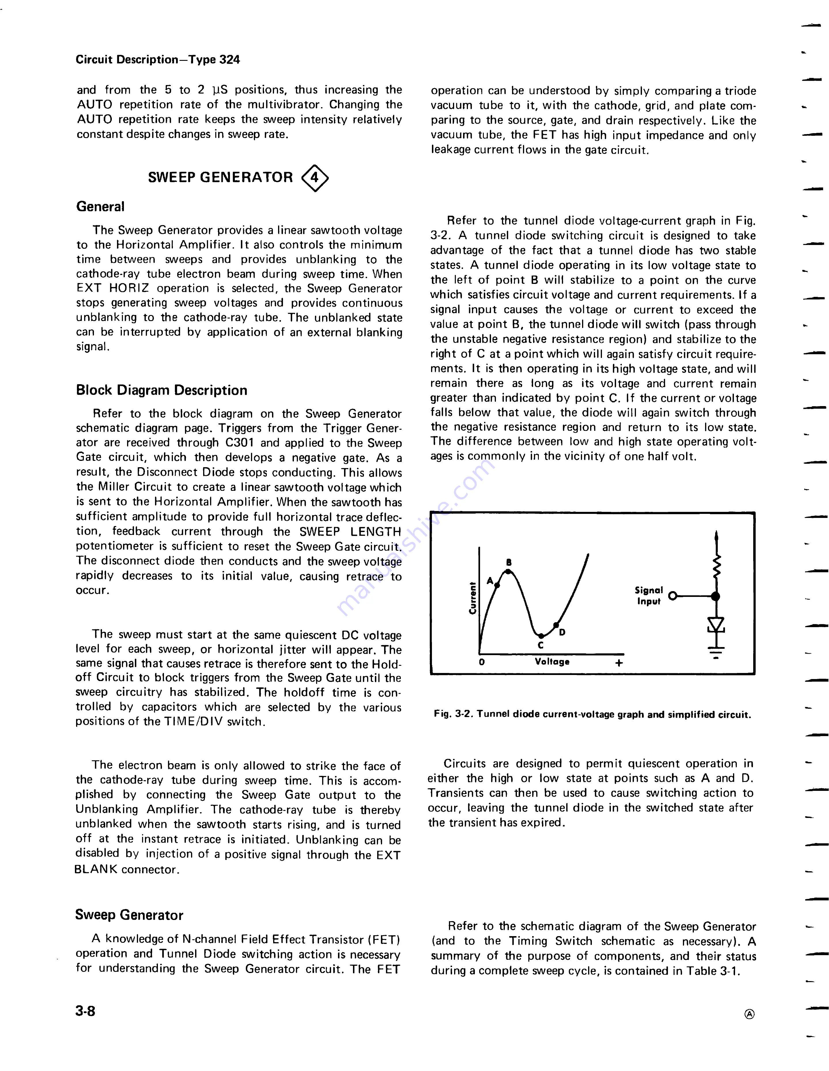
Refer to the tunnel diode voltage-current graph in Fig.
3-2. A tunnel diode switching circuit is designed to take
advantage of the fact that a tunnel diode has two stable
states. A tunnel diode operating in its low voltage state to
the left of point B will stabilize to a point on the curve
which satisfies circuit voltage and current requirements. If a
signal input causes the voltage or current to exceed the
value at point B, the tunnel diode will switch (pass through
the unstable negative resistance region) and stabilize to the
right of C at a point which will again satisfy circuit require
ments. It is then operating in its high voltage state, and will
remain there as long as its voltage and current remain
greater than indicated by point C. If the current or voltage
falls below that value, the diode will again switch through
the negative resistance region and return to its low state.
The difference between low and high state operating volt
ages is commonly in the vicinity of one half volt.
Fig. 3-2. Tunnel diode current-voltage graph and simplified circuit.
The electron beam is only allowed to strike the face of
the cathode-ray tube during sweep time. This is accom
plished by connecting the Sweep Gate output to the
Unblanking Amplifier. The cathode-ray tube is thereby
unblanked when the sawtooth starts rising, and is turned
off at the instant retrace is initiated. Unblanking can be
disabled by injection of a positive signal through the EXT
BLANK connector.
Circuits are designed to permit quiescent operation in
either the high or low state at points such as A and D.
Transients can then be used to cause switching action to
occur, leaving the tunnel diode in the switched state after
the transient has expired.
Sweep Generator
A knowledge of N-channel Field Effect Transistor (FET)
operation and Tunnel Diode switching action is necessary
for understanding the Sweep Generator circuit. The FET
Refer to the schematic diagram of the Sweep Generator
(and to the Timing Switch schematic as necessary). A
summary of the purpose of components, and their status
during a complete sweep cycle, is contained in Table 3-1.
3-8
®