Table of Contents
iv
P7350 5 GHz Differential Probe Instruction Manual
List of Figures
Figure 1: P7350 differential probe featuring the
TekConnect interface
1
. . . . . . . . . . . . . . . . . . . . . . . . . . . . . .
Figure 2: Connecting and disconnecting the probe
2
. . . . . . . . . .
Figure 3: Probe functional check connections
3
. . . . . . . . . . . . .
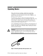
Figure 4: Protect the probe tips with the protective cover
11
. . . .
Figure 5: Using the variable spacing adapter
13
. . . . . . . . . . . . . .
Figure 6: Using the TwinFoot adapter
13
. . . . . . . . . . . . . . . . . . . .
Figure 7: Typical probe input model
14
. . . . . . . . . . . . . . . . . . . . .
Figure 8: Probe ground input
15
. . . . . . . . . . . . . . . . . . . . . . . . . . .
Figure 9: Typical effects on a signal using probe tip adapters
16
.
Figure 10: Simplified model of a differential amplifier
18
. . . . . .
Figure 11: Twisting the input leads
20
. . . . . . . . . . . . . . . . . . . . . .
Figure 12: Typical common- and differential-mode gain plots
24
Figure 13: Typical differential input impedance vs frequency
25
.
Figure 14: Typical bandwidth
25
. . . . . . . . . . . . . . . . . . . . . . . . . .
Figure 15: Probe head and compensation box dimensions
27
. . . .
Figure 16: Variable spacing adapter dimensions
28
. . . . . . . . . . . .
Figure 17: Square pin adapter dimensions
28
. . . . . . . . . . . . . . . .
Figure 18: TekConnect Interface Calibration Adapter
31
. . . . . . .
Figure 19: Probe Calibration Fixture
33
. . . . . . . . . . . . . . . . . . . . .
Figure 20: Probe Calibration Fixture test points
34
. . . . . . . . . . . .
Figure 21: Setup for the output offset voltage test
35
. . . . . . . . . .
Figure 22: DC Gain Accuracy setup
36
. . . . . . . . . . . . . . . . . . . . .
Figure 23: Test system rise time setup
38
. . . . . . . . . . . . . . . . . . .
Figure 24: Test system rise time setup with probe
40
. . . . . . . . . .
Figure 25: Verifying both probe pins are contacting the
DM test points
41
. . . . . . . . . . . . . . . . . . . . . . . . . . . . . . . . . . .
Figure 26: P7350 replaceable parts
47
. . . . . . . . . . . . . . . . . . . . . .
Figure 27: P7350 standard accessories
49
. . . . . . . . . . . . . . . . . . .
Figure 28: P7350 optional accessories
51
. . . . . . . . . . . . . . . . . . .


