background image

21 | 

P a g e


GNSS Receiver


L1/GLONASS (1575.42 / 1598-1606 MHz) Frequency, C/A Code, 32 Channel, parallel-tracking receiver 

Position 

Accuracy 

Horizontal 

<9 m (90%) 

Altitude 

<18 m (90%) 

Timing Accuracy 

<15 ns (1 sigma) to UTC 

Sensitivity 

Acquisition 

-148 dBm 

Tracking 

-160 dBm 

Antenna output voltage 

5 V 

Antenna output current 

100 mA (max) 

Summary of Contents for NTS 02-G

Page 1: ...NTS 02 G USER MANUAL Third Edition Copyright 2022 ...

Page 2: ...RIG B Input 3 pin 3 81 mm Connector 13 P3 Programmable Output 3 pin 3 81 mm Connector 13 P4 Sync and Antenna Alarm Relays 4 pin 3 81 mm Connector 14 ADMIN ETH 1 Ethernet Administration Port RJ 45 14 ETH 2 and ETH 3 Ethernet Communication Ports RJ 45 14 4 Software 15 Configuration Tool 15 USB driver 15 5 Installation 16 Identification 16 Location 16 Power Supply 16 Hazardous Voltage 16 Mounting the...

Page 3: ...3 P a g e Slave Only Option Fiber input 19 8 Appendix 20 NTS 02 G Specifications 20 9 Warranty Statement 22 10 Notes 22 ...

Page 4: ...2 G product is ideally suited for use in industrial environments and can provide NTP or PTP server functions to multiple independent Ethernet networks All NTS 02 G units feature a front panel display see Figure 1 giving visual feedback about the time data being generated on the outputs LED indicators provide at a glance status information Figure 1 NTS 02 G front and back panels The NTS 02 G featur...

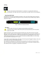
Page 5: ... display shows a copyright message along with the serial number and NTS 02 G firmware version see figure 3a Approximately 10 seconds after power up if the NTS 02 G is operating in its default mode as a GNSS synchronized grandmaster clock then the display changes automatically to indicate that it is waiting for satellites see figure 3b Once one or more satellites have been discovered it transitions...

Page 6: ...the day is Tuesday LST denotes Local Standard Time If daylight savings time is active the LST in screen 3d changes to LDT denoting Local Daylight Time Figure 3e shows the UTC time and date which is 11 16 53 on the evening of Monday 17th March 2013 Figure 3g shows the basic Ethernet network settings for Admin ETH1 port In this example it shows the port has been configured with a fixed static IP add...

Page 7: ...mally again Satellites tracked 0 9 0 9 A E 10 14 F 14 This digit represents the number of satellites currently being used to compute the time solution A 0 value means that no updated time solution is available out of lock condition If this condition persists for the Holdover time the NTS 02 G will indicate out of sync as described under LED Indicators section below GNSS Receiver Mode A NTS 02 G in...

Page 8: ...ne level The LCD will cycle from the darkest to the lightest if the button is pressed when on the lightest setting To exit the Contrast Adjustment Mode hold down the button on the front panel for approximately 3 seconds again The button will return to normal operation after this LED Indicators The SYNC LED shows the status of the sync source The various states are shown as follows Off The NTS 02 G...

Page 9: ... circuit or if the antenna connected has a higher current drain specification N A Antenna Fault This alarm is generated if there is high current or low current detected on the antenna input Factory Reset Cycle Power Factory Reset Armed This alarm is generated if the Forgotten Password Reset Factory Reset Process is enabled and has been initiated by the user IRIG No IRIG B Input No valid IRIG B sou...

Page 10: ...figuration options as the Admin Ethernet port 1 The configuration software supplied with the NTS 02 G supports both USB and Ethernet configuration A USB driver for the NTS 02 G can be downloaded from www support tekron com The NTS 02 G can be configured through the USB admin port only to add an extra security layer Figure 5 USB Admin Port ...

Page 11: ...ut voltage range is marked on the label located below the P1 connector Check the label on the unit base for power supply voltage ratings before applying power Earth Stud M4 Nut An M4 bolt to chassis is provided for earthing of cable shields It is recommended that the bolt is bonded to earth using a cable terminated with a ring terminal This provides a safe discharge path in the event of a short ci...

Page 12: ...that the Tekron supplied antenna is used CNT 240 32 8 dB 100 m 10dB 100ft Plus 1 dB connector Approximate optimum length range 15m to 60m 50 ft 197 ft Approximate maximum length range 15m to 76m 50 ft 250 ft CNT 400 16 73 dB 100 m Plus 1 dB connector Approximate optimum length range 30m to 120 m 99 ft 394 ft Approximate maximum length range 30m to 150m 99 ft 493 ft A lightning protection device sh...

Page 13: ...ctor P3 Programmable Output 3 pin 3 81 mm Connector This port transmits an un modulated IRIG B programmable pulse or a DCF77 signal using RS422 levels on pins and of the mating connector The default output is an un modulated IRIG B signal IRIG B004 with C37 118 1 extensions It can be used as the master source signal to drive the P2 inputs of one or many slave NTS 02 03 G units or other end devices...

Page 14: ...m This alarm is active contact open when the unit is not synchronized and is not in the holdover state ADMIN ETH 1 Ethernet Administration Port RJ 45 The Ethernet administration port ETH1 features an RJ 45 connector and supports 10 100 Mbps Auto MDI X and Auto Negotiate The port indicator LEDs conveys the Link LNK and Activity ACT status for the port This port is used to configure NTS 02 G setting...

Page 15: ...ith DHCP enabled for automatic IP address assignment with a fall back to link local addressing 169 254 xxx xxx if no DHCP server is present Default Username admin Default Password Password Note The user is required to change the default password on first login USB driver The USB driver can be downloaded from the NTS 02 G product page of the Tekron website https tekron com productsnetwork time serv...

Page 16: ... be accessed only using a lock and key or other means of security Installation is to be done by suitably qualified personnel Power Supply The input voltage range is marked on the product label on the base or side of the unit Do not apply voltage outside the range noted DC power should be applied to pins L and N DC polarity is not critical but only pin L is fused internally It is recommended to con...

Page 17: ...1 The time required to achieve tracking and synchronization given a good view of the sky is typically within one minute and 30 seconds The NTS 02 G will usually take under one minute to synchronize to the GNSS source then it will spend an additional 30 seconds at most validating that the sync source is stable before reporting that it is in sync The NTS 02 G performs stability validation on all inc...

Page 18: ... order to maximize security and must be enabled via the Tekron Configuration Tool before it can be used When disabled there is no method to gain full access to the unit without the administrator password and if the administrator password is forgotten the unit must be returned to Tekron for reprogramming at the customer s expense This feature may be permanently disabled by Tekron on request For fur...

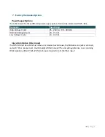
Page 19: ... pin 85 250 Vac 90 300 Vdc Medium Voltage 3 pin 20 75 Vdc Low Voltage 3 pin 14 36 Vdc Slave Only Option Fiber input The NTS 02 G can be ordered as a slave only device in which case the SMA antenna jack is removed and an ST Fiber receiver port multi mode is fitted instead The unit will synchronize to an incoming IRIG B signal on either P2 RS422 format signal required or on the Fiber input ...

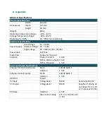
Page 20: ...90 300 Vdc 85 250 Vac Power drain 6 W max Protection Surge and Transient Isolation Power In to NTS 3 0 kV NTS to Alarm outputs 3 5 kV NTS to Ethernet 1 5 kV Input and Output Specifications Ethernet Port Administrator RJ 45 10 100 BASE T Isolation 1 5 kV Ethernet Ports 2 and 3 RJ 45 10 100 BASE T Isolation 1 5 kV USB Port Type B P2 Input Voltage level RS422 Sensitivity 200 mV P3 Output Voltage leve...

Page 21: ...z Frequency C A Code 32 Channel parallel tracking receiver Position Accuracy Horizontal 9 m 90 Altitude 18 m 90 Timing Accuracy 15 ns 1 sigma to UTC Sensitivity Acquisition 148 dBm Tracking 160 dBm Antenna output voltage 5 V Antenna output current 100 mA max ...

Page 22: ...e The manufacturer assumes no responsibility for any errors that may appear in this manual Ethernet is a trademark of XEROX Corporation Windows Windows 95 Windows 98 Windows 2000 Windows NT Windows XP Windows Vista and Windows 7 are trademarks of Microsoft Corp Copyright 2014 Tekron International Ltd All rights reserved No part of the contents of this document may be transmitted or reproduced in a...

Reviews: