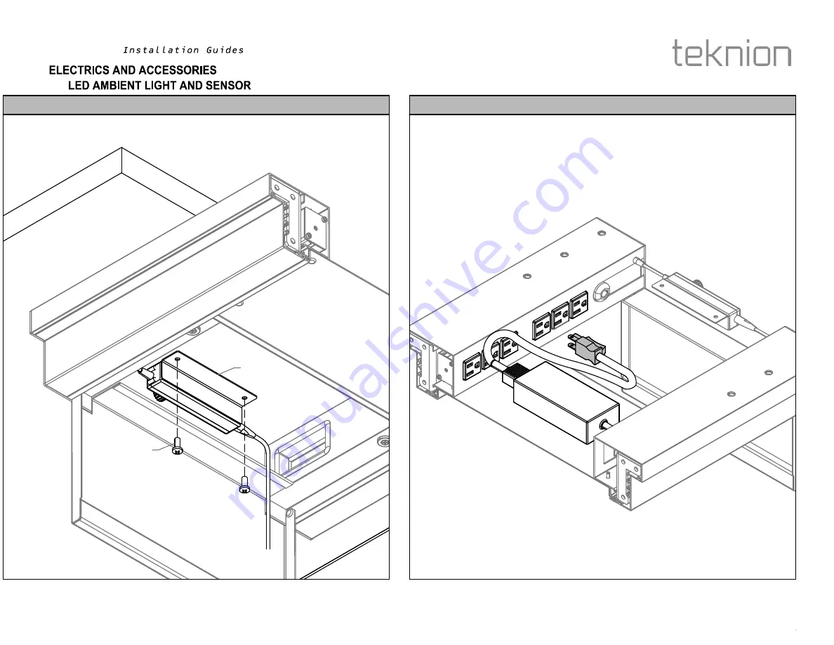
STEP 11a: Place AC Adapter to tray of Bridge. Plug to any available socket.
STEP 10a: Fasten Sensor to underside of Worksurface using screws provided
B
A2
Section:Description:
Page No:
Date: SID_101
8 of 12
Sep 2012
FASTEN SENSOR
PLUG
sidewise
Page 1: ...Meeting Hub with Coat Shelf SWDMA Desk Height Rectangular Solo Desk with Coat Shelf SWDSA 002 Jul 2015 Desk Height Rectangular Solo Desk with Shelf SWDSB Desk Height Rectangular Solo Desk with Coat D...
Page 2: ...X80 61011 x2 F Locking Screw E01 50793 x3 D Pedestal Leg Assembly N80 67012 24 x1 Or N80 67012 29 x1 Or N80 67012 36 x1 G1 Round Surface SWWDM486 x1 G2 D Surface SWWDB36 XX XX 6 x1 OR A D I Wire Mana...
Page 3: ...Covers NOTE Re insert Covers after Worksurface Support and Worksurface are installed A3 A2 A1 A3 A NOTE Re insert Covers after Worksurface Support and Worksurface are installed H STEP 1 Section Descr...
Page 4: ...STEP 3 Secure Worksurface Support and Tower with Screws B DETAIL VIEW Section Description Page No Date SECURE SUPPORT ASSEMBLY Sep 2012 3 of 15 SID_001 sidewise...
Page 5: ...ff the cover on Adhesive Strip NOTE Please refer to Specification Drawing for the length of Tube I J I J NOTE Please refer to Specification Drawing for the length of Tube NOTE Please cut the 280mm Wir...
Page 6: ...be as shown for Dual Sided Desk with 36 wide Storage Tower SIDE VIEW TOP VIEW BOTTOM VIEW I I I Section Description Page No Date ATTACH WIRE MANAGEMENT TUBE DUAL SIDED DESK HEIGHT WITH 36 WIDE STORAGE...
Page 7: ...e Management Tube as shown for Counter Height Storage Tower SIDE VIEW TOP VIEW BOTTOM VIEW J I I J J Section Description Page No Date ATTACH WIRE MANAGEMENT TUBE COUNTER HEIGHT STORAGE TOWER Sep 2012...
Page 8: ...shown for Single Side Desk Height with 24 Wide Storage Tower SIDE VIEW TOP VIEW BOTTOM VIEW I I J J I J Section Description Page No Date ATTACH WIRE MANAGEMENT TUBE SINGLE SIDED DESK HEIGHT WITH 24 W...
Page 9: ...shown for Single Side Desk Height with 30 Wide Storage Tower SIDE VIEW TOP VIEW BOTTOM VIEW I I J J J I Section Description Page No Date ATTACH WIRE MANAGEMENT TUBE SINGLE SIDED DESK HEIGHT WITH 30 W...
Page 10: ...n Cable into Storage Tower STEP 6 Guide Cable through Worksurface Support BOTTOM VIEW Section Description Page No Date SID_001 9 of 15 Sep 2012 GUIDE CABLE THROUGH SUPPORT RUN CABLE INTO STORAGE TOWER...
Page 11: ...t Cable into Wire Management Tube STEP 8a Insert Cable into Wire Management Tube BOTTOM VIEW Section Description Page No Date SID_001 10 of 15 Sep 2012 INSERT CABLE DESK HEIGHT INSERT CABLE COUNTER HE...
Page 12: ...the Bridge Connection NOTE Please refer to next page and Specification Drawing for the height of the Pedestal Leg STEP 9 Remove Locking Screws from Pedestal Leg F D Section Description Page No Date SI...
Page 13: ...Align the pilot holes under Worksurface corresponding to Pedestal Leg and Worksurface Support SIDE VIEW FINISHED FLOOR ALIGN ALIGN NOTE Align the pilot holes under Worksurface corresponding to Pedesta...
Page 14: ...s on Pedestal Leg as shown to lock it in the adjusted height STEP 11 Lay Worksurface on Bridge Connection and Pedestal Leg then level it Section Description Page No Date SID_001 13 of 15 Sep 2012 LEVE...
Page 15: ...STEP 13 Secure Worksurface on Support and Pedestal Leg with Screws E G2 C DETAIL VIEW DETAIL VIEW Section Description Page No Date SECURE WORKSURFACE Sep 2012 14 of 15 SID_001 sidewise...
Page 16: ...E Make sure to use the Support Cover with hole for the Power Bar side NOTE Make sure to use the Support Cover with hole for the Power Bar side Section Description Page No Date RE INSERT WORKSURFACE SU...
Page 17: ...Tube With Adhesive Strip B11 67000 29 x 1 I Wire Management Tube With Adhesive Strip B11 67000 11 x 1 F Foot Frame Assembly Open N80 64157 24 29 x1 Or N80 64157 30 29 x1 Or N80 64157 36 29 x1 Or N80 6...
Page 18: ...port Covers NOTE Re insert Covers after Worksurface Support and Worksurface are installed A3 A2 A1 A3 A NOTE Re insert Covers after Worksurface Support and Worksurface are installed E Section Descript...
Page 19: ...STEP 3 Secure Worksurface Support and Tower with Screws B DETAIL VIEW Section Description Page No Date SECURE SUPPORT ASSEMBLY Jul 2015 3 of 15 SID_002 sidewise...
Page 20: ...ff the cover on Adhesive Strip NOTE Please refer to Specification Drawing for the length of Tube I H I H NOTE Please refer to Specification Drawing for the length of Tube NOTE Please cut the 280mm Wir...
Page 21: ...be as shown for Dual Sided Desk with 36 wide Storage Tower SIDE VIEW TOP VIEW BOTTOM VIEW H H H Section Description Page No Date ATTACH WIRE MANAGEMENT TUBE DUAL SIDED DESK HEIGHT WITH 36 WIDE STORAGE...
Page 22: ...e Management Tube as shown for Counter Height Storage Tower SIDE VIEW TOP VIEW BOTTOM VIEW I H H I I Section Description Page No Date ATTACH WIRE MANAGEMENT TUBE COUNTER HEIGHT STORAGE TOWER Jul 2015...
Page 23: ...or Single Side Desk Height with 24 Wide Storage Tower Page No Page No SIDE VIEW TOP VIEW BOTTOM VIEW H H I I H I Section Description Page No Date ATTACH WIRE MANAGEMENT TUBE SINGLE SIDED DESK HEIGHT W...
Page 24: ...shown for Single Side Desk Height with 30 Wide Storage Tower SIDE VIEW TOP VIEW BOTTOM VIEW H H I I I H Section Description Page No Date ATTACH WIRE MANAGEMENT TUBE SINGLE SIDED DESK HEIGHT WITH 30 W...
Page 25: ...n Cable into Storage Tower STEP 6 Guide Cable through Worksurface Support BOTTOM VIEW Section Description Page No Date SID_002 9 of 15 Jul 2015 GUIDE CABLE THROUGH SUPPORT RUN CABLE INTO STORAGE TOWER...
Page 26: ...e into Wire Management Tube STEP 8a Insert Cable into Wire Management Tube BOTTOM VIEW BOTTOM VIEW Section Description Page No Date SID_002 10 of 15 Jul 2015 INSERT CABLE DESK HEIGHT INSERT CABLE COUN...
Page 27: ...eight for the Frame Leg NOTE Please refer to next page or Specification Drawing for the correct height of the Frame Leg BOTTOM VIEW DETAIL VIEW F Section Description Page No Date ADJUST FRAME LEG HEIG...
Page 28: ...t Align the pilot holes under Worksurface corresponding to Frame Leg and Worksurface Support SIDE VIEW FINISHED FLOOR ALIGN ALIGN NOTE Align the pilot holes under Worksurface corresponding to Frame Le...
Page 29: ...STEP 10 Lay Worksurface on Leg and Worksurface Support then level it FINISHED FLOOR D Section Description Page No Date LEVELING WITH WORKSURFACE Jul 2015 13 of 15 SID_002 sidewise...
Page 30: ...STEP 11 Secure Worksurface on Support and Frame Leg with Screws G C DETAIL VIEW DETAIL VIEW BOTTOM VIEW Section Description Page No Date SECURE WORKSURFACE Jul 2015 14 of 15 SID_002 sidewise...
Page 31: ...E Make sure to use the Support Cover with hole for the Power Bar side NOTE Make sure to use the Support Cover with hole for the Power Bar side Section Description Page No Date RE INSERT WORKSURFACE SU...
Page 32: ...refer to Installation Guide SID_201 to remove all Drawers and Shelves before proceeding this instrustion NOTE SWRA shown SWRA or SWRC SWUC F 10 1 1 2 Wood Screw Phillips Drive 6 PLCS Q20 0529 Fixed Bo...
Page 33: ...er to Installation Guide SID_101 for LED installation B NOTE Option with LED installed shown Please refer to Installation Guide SID_101 for LED installation NOTE Option without LED installed shown REV...
Page 34: ...cliner with Storage Tower Secure Storage and Brackets on Recliner with Screws C C REVERSE VIEW DETAIL VIEW SIDE VIEW Section Description Page No Date ATTACH RECLINER AND STORAGE TOWER Jul 2015 3 of 8...
Page 35: ...STEP 3 Insert Electric Bar into the highlighted location A A SIDE VIEW Section Description Page No Date INSERT ELECTRIC BAR Jul 2015 4 of 8 SID_003 sidewise...
Page 36: ...STEP 4 Secure the Electric Bar to Recliner as shown D D SIDE VIEW REVERSE VIEW DETAIL VIEW Section Description Page No Date SECURE ELECTRIC BAR Jul 2015 5 of 8 SID_003 sidewise...
Page 37: ...STEP 5 Drill through the pilot holes on Recliner from underneath Section Description Page No Date DRILL THROUGH PILOT HOLES Jul 2015 6of 8 SID_003 sidewise...
Page 38: ...STEP 6 Align pilot holes on Cushion and Recliner then secure them with Screws as shown H F SIDE VIEW BOTTOM VIEW F H Section Description Page No Date SECURE SEAT Jul 2015 7 of 8 SID_003 sidewise...
Page 39: ...hown Important For Loose Bolster application please place the Bolster on Seat G REVERSE VIEW F Important For Loose Bolster application please place the Bolster on Seat without fastening it to Storage...
Page 40: ...6 1 2 Wood Screw FS6 1 2 x 4 C Magnet 3M Double Sided Tape x 2 D Wire Management Tube with Adhesive Strip B11 67000 29 x 1 A1 A2 NOTE STSWDWXXYY72XXN Shown as example LED Ambient Light and Occupancy S...
Page 41: ...f Tower Mark with pencil for final location STEP 1 Feed power cable through top of Tower LED Power Cable Align Mark EQ EQ TOP VIEW Section Description Page No Date SID_101 2 of 12 Sep 2012 CABLE THROU...
Page 42: ...rface of Tower STEP 3 Turn over LED light and locate metal strips inserted at the bottom of LED light NOTE Make sure adhesive side of magnet is facing upwards C A1 Section Description Page No Date SID...
Page 43: ...STEP 5 Plug Power Cable to LED STEP 4b Fasten Led to Tower with screws provided B LED Power Cable Section Description Page No Date SID_101 4 of 12 Sep 2012 FASTEN TO TOWER PLUG CABLE TO LED sidewise...
Page 44: ...STEP 7 Attach Wire Management Tube as shown STEP 6 Peel off the cover on Adhesive Strip D Adhesive Side Section Description Page No Date SID_101 5 of 12 Sep 2012 BOTTOM VIEW RELEASE TRIGGERS sidewise...
Page 45: ...a Insert Cable into Wire Management Tube and feed through opening located at the side of Tower LED Power Cable LED Power Cable Section Description Page No Date INSERT CABLE Sep 2012 6 of 12 SID_101 si...
Page 46: ...STEP 9a Flip down tray of bridge Worksurface Tower Section Description Page No Date FLIP DOWN TRAY Sep 2012 7 of 12 SID_101 sidewise...
Page 47: ...Adapter to tray of Bridge Plug to any available socket STEP 10a Fasten Sensor to underside of Worksurface using screws provided B A2 Section Description Page No Date SID_101 8 of 12 Sep 2012 FASTEN SE...
Page 48: ...STEP 12a Plug LED Power Cable previously passed through opening of tower to Sensor LED Power Cable A2 LED Power Cable Section Description Page No Date PLUG TO SENSOR Sep 2012 9 of 12 SID_101 sidewise...
Page 49: ...STEP 8b Insert Cable into Wire Management Tube and feed through opening located at the side of Tower LED Power Cable Section Description Page No Date PLUG TO SENSOR Sep 2012 10 of 12 SID_101 sidewise...
Page 50: ...ten Sensor as shown using screws provided STEP 9b Bring Sensor to the inside opening of Recliner 6 EQ EQ A2 A2 B Section Description Page No Date SID_101 11 of 12 Sep 2012 SENSOR TO OPENING FASTEN SEN...
Page 51: ...Sensor and run all Cables through the cut out on Recliner NOTE Refer to Installation Guide SID_003 for Lounge Recliner Installation REVERSE VIEW Section Description Page No Date LED CABLE TO SENSOR Se...
Page 52: ...roduct support teknion com B Insert Element Bracket A15 64622 ww x1 C Accessory Inset Element N80 61588 13 ww x1 Or N80 61588 15 ww x1 B MULTI DRAWER C Accessory Rail Element SWDA Part and Product Ide...
Page 53: ...sive covers STEP 1 Attach Bracket onto the highlighted location under the fixed shelf as shown and secure it with Screws A A C SIDE VIEW B B Section Description Page No Date SID_102 2 of 3 Sep 2012 BR...
Page 54: ...tach the adhesive strips to the back panel STEP 3 Insert Inset Element to the Bracket at an angle as shown above C C C SIDE VIEW SIDE VIEW Section Description Page No Date SID_102 3 of 3 Sep 2012 INSE...
Page 55: ...pport teknion com B Self Tap Wood Screw E04 50005 x 10 A NOTE Refer to Install Guide SID_201 if Shelf Installation Removal from Rail is required Pull Out CPU Shelf SWPS Part and Product Identification...
Page 56: ...e bottom of Tower Mark areas shown to fasten CPU Shelf to tower STEP 1 Place CPU Shelf at the bottom shelf cavity of Tower A Align Section Description Page No Date SID_103 2 of 3 Sep 2012 CPU SHELF TO...
Page 57: ...STEP 4 Fasten both Brackets with screws provided STEP 3 Pull Shelf so Tracks are fully extended B Section Description Page No Date SID_103 3 of 3 Sep 2012 PULL OUT SHELF FASTEN TO TOWER sidewise...
Page 58: ...As per order D End Cap A25 61021L x 1 and A25 61021R x 1 E Plastic Gasket B03 50077 x 1 F Modesty Panel Cover A21 50179 x 2 G 1 4 20 x 1 4 Flat Point Hex Socket Screw E01 50308 x As per order H 14 x...
Page 59: ...ration shows location for Modesty Panel Underside View of Worksurface EQ EQ EQ EQ Outline of Frame Leg Outline of Support Underside View of Worksurface 16 max 16 max Section Description Page No Date S...
Page 60: ...semble Brackets Modesty Panel Cover and End Caps together as show on illustration C F F Underside View of Worksurface C D Section Description Page No Date SID_104a 3 of 6 Jul 2015 ASSEMBLE BRACKETS CO...
Page 61: ...STEP 4 Fasten Bracket and Spacer to underside of Worksurface H C B Section Description Page No Date FASTEN BRACKET SPACER TO WORKSURFACE Jul 2015 4 of 6 SID_104a sidewise...
Page 62: ...Then line up Gasket to cavity of Endcap NOTE The rubber side of the plastic extrusion must be installed the opposite side of the socket set screws Rubber G A E Section Description Page No Date SID_10...
Page 63: ...STEP 7 Fasten Cover to Bracket as shown on illustration Section Description Page No Date ATTACH PANEL COVER Jul 2015 6 of 6 SID_104a sidewise...
Page 64: ...upport please contact product support teknion com C 1 4 20 x 5 8 Quad Pan Head Black E01 50403 x 4 D 12 x 3 4 Quad Pan Head Wood Screw E04 50017 x 4 Solid Modesty Panel SWMPS Part and Product Identifi...
Page 65: ...TE To determine the position of brackets align holes of the Modesty Panel with the holes of the Worksurface If NO alignment hole provided use widest Bracket position C B A Section Description Page No...
Page 66: ...3 Place Modesty Panel as shown on illustration A Underside View of Worksurface A EQ EQ D EQ EQ Outline of Frame Leg Outline of Support Underside View of Worksurface Section Description Page No Date S...
Page 67: ...ve Safety Stopper NOTE Safety Stopper is placed in Tower so Drawers are not pulled too far out Safety Stopper Section Description Page No Date SID_201 1 of 7 Sep 2012 SAFETY STOPPER REMOVE SAFETY STOP...
Page 68: ...ten other Track STEP 2a Pull Drawer so Tracks are fully extended Unfasten screw that holds Track and Bracket together Section Description Page No Date SID_201 2 of 7 Sep 2012 UNFASTEN TRACK UNFASTEN T...
Page 69: ...k so it unhooks from Rail NOTE Make sure Track stays in the full extended position STEP 4a Lift front of Drawer off of Track Section Description Page No Date SID_201 3 of 7 Sep 2012 LIFT FRONT ALIGN S...
Page 70: ...STEP 6a Lift Drawer off Track and remove NOTE To reinstall reverse procedure Section Description Page No Date LIFT AND REMOVE Sep 2012 4 of 7 SID_201 sidewise...
Page 71: ...out Drawer so that Track is in its full extended position Squeeze Triggers on the bottom of Drawer to release from Drawer Tracks Section Description Page No Date PULL OUT DRAWER Sep 2012 5 of 7 SID_2...
Page 72: ...STEP 2b Lift off Track and remove Section Description Page No Date LIFT AND REMOVE Sep 2012 6 of 7 SID_201 sidewise...
Page 73: ...STEP 3b To reinstall reverse procedure NOTE when reinstalling make sure Bracket rests on the side of the Track Section Description Page No Date REINSTALLATION Sep 2012 7 of 7 SID_201 sidewise...