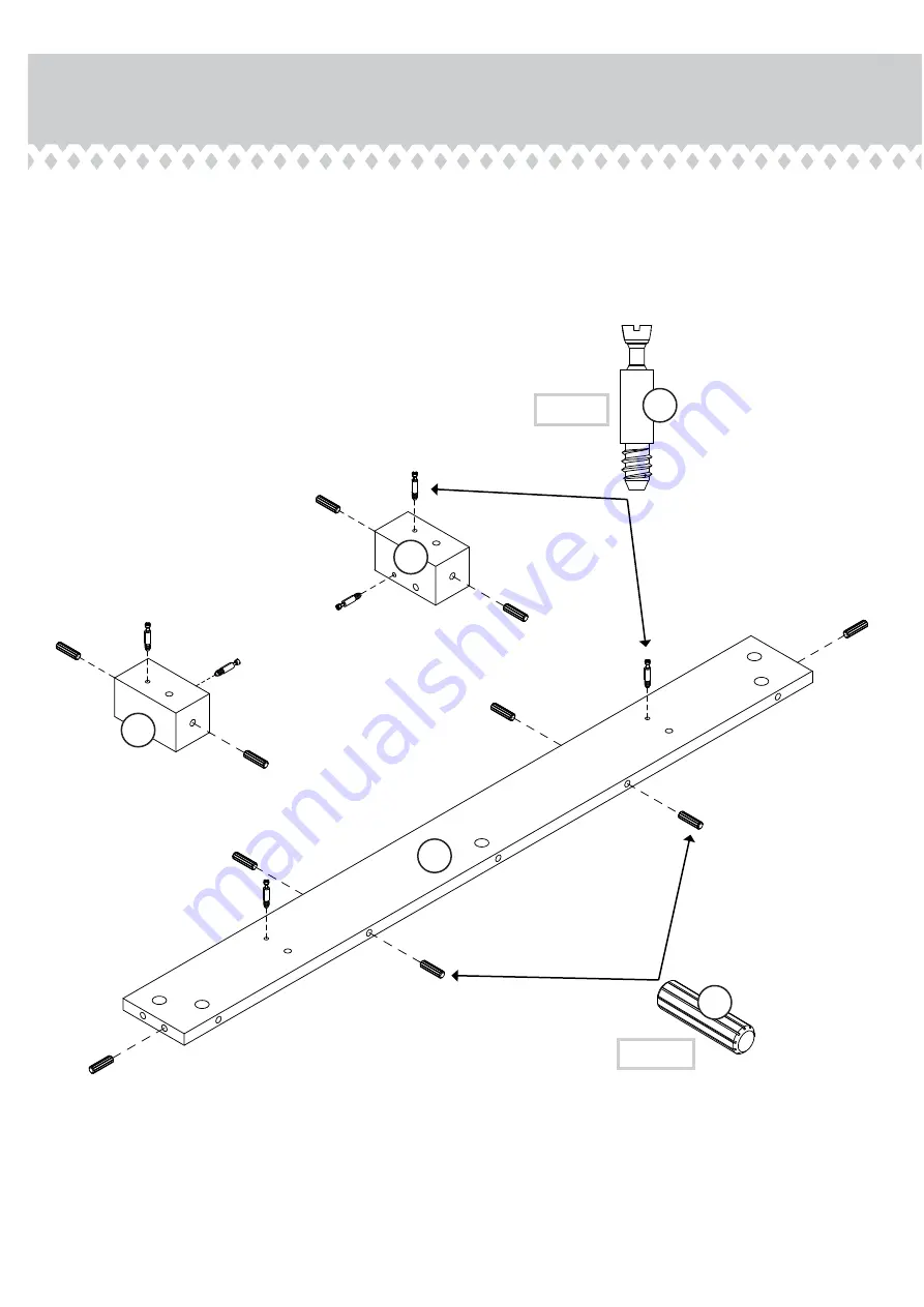
Step 3
419232
å
Turn six CAM SCREWS (4) into the exact holes shown inthe REAR CORNERS (L and M) and BACK (H).
Insert ten WOOD DOWELS (7) into the exact holes shownin the REAR CORNERS (L and M) and BACK (H).
4
(6 used)
7
(10 used)
H
L
M
Page 1: ...www teknikoffice co uk NOTE THIS INSTRUCTION BOOKLET CONTAINS IMPORTANT SAFETY INFORMATION PLEASE READ AND KEEP FOR FUTURE REFERENCE Canal Heights TV Stand 5419232 Smart stand for the idiot box Teknik ...
Page 2: ...our TV Compare it to the diagram below before you begin assembly This Sauder unit is designed for use with televisions weighing less than 50 pounds Never use with a TV that weighs more The size of the television front to back and side to side must fit within the space defined in the diagram Never place the front edge of the TV past the front edge of the TV support shelf or stop molding if equipped N...
Page 3: ...HT END 1 B LEFT END 1 C RIGHT UPRIGHT 1 D LEFT UPRIGHT 1 E TOP 1 F BOTTOM 1 G SHELF 2 H BACK 1 I RIGHT FRONT PANEL 1 J LEFT FRONT PANEL 1 K FRONT CORNER 2 L RIGHT REAR CORNER 1 M LEFT REAR CORNER 1 N RIGHT LEG ASSEMBLY 1 O LEFT LEG ASSEMBLY 1 P BRACE 2 Q BACK BRACE 2 R SHELF BRACE 2 S DRAWER FRONT 1 T DRAWER BACK 1 U RIGHT DRAWER SIDE 1 V LEFT DRAWER SIDE 1 W DRAWER BOTTOM 1 X DRAWER BRACE 1 Page ...
Page 4: ... 4 5 SMALL CAM SCREW 4 6 1 1 4 FLAT HEAD SCREW 16 14 WOOD DOWEL 40 7 SMALL WOOD DOWEL 2 8 WARNING LABEL 1 18 WARNING Never use this furniture with a TV that is too large or too heavy Severe injury or death can occur The TV and furniture will be unstable and may tip The TV must less than 50 lbs The base of the TV must be able to sit completely on this shelf Refer to instruction book for complete sa...
Page 5: ...Step 1 å Assemble your unit on a carpeted floor or on the empty carton to avoid scratching your unit or the floor å Insert thirteen CAM SCREWS 4 into the TOP E Page 5 E 4 13 used ...
Page 6: ...sy å Fasten the EXTENSION RAILS 1 to the UPRIGHTS C and D Use six 1 2 PAN HEAD SCREWS 17 å NOTE Use the exact holes shown in the RAILS å Insert sixteen WOOD DOWELS 7 into the exact holes shown in the ENDS A and B and UPRIGHTS C and D C B A D Open end Open end 2 1 1 1 Mounting holes Open end 7 16 used 1 2 PAN HEAD SCREW 6 used in this step 17 1 ...
Page 7: ...232 å Turn six CAM SCREWS 4 into the exact holes shown in the REAR CORNERS L and M and BACK H å Insert ten WOOD DOWELS 7 into the exact holes shown in the REAR CORNERS L and M and BACK H 4 6 used 7 10 used H L M ...
Page 8: ...ard the edge of the board H L M å Insert two HIDDEN CAMS 3 into the BACK H å Fasten the REAR CORNERS L and M to the BACK H Tighten two HIDDEN CAMS å NOTE Be sure the WOOD DOWELS in the edges of the BACK insert into the holes in the REAR CORNERS 3 3 ...
Page 9: ...ix CAM SCREWS 4 into the exact holes shown in the FRONT PANELS I and J and FRONT CORNERS K å Insert fourteen WOOD DOWELS 7 into the exact holes shown in the FRONT PANELS I and J and FRONT CORNERS K 4 6 used 7 14 used K K J I ...
Page 10: ...CAMS 3 into the FRONT PANELS I and J å Fasten the FRONT CORNERS K to the FRONT PANELS I and J Tighten two HIDDEN CAMS å NOTE Be sure the WOOD DOWELS in the edges of the FRONT PANELS insert into the holes in the FRONT CORNERS 3 3 K K J I ...
Page 11: ...B and UPRIGHTS C and D å Fasten the ENDS A and B and UPRIGHTS C and D to the FRONT PANELS I and J and FRONT CORNERS K Tighten four HIDDEN CAMS å NOTE Be sure the WOOD DOWELS in the edges of the ENDS and UPRIGHTS insert into the holes in the FRONT PANELS and FRONT CORNERS 3 4 used ...
Page 12: ...A and B and UPRIGHTS C and D å Fasten the ENDS A and B and UPRIGHTS C and D to the BACK H and REAR CORNERS L and M Tighten four HIDDEN CAMS å NOTE Be sure the WOOD DOWELS in the edges of the ENDS and UPRIGHTS insert into the holes in the BACK and REAR CORNERS M L 3 4 used ...
Page 13: ...GHTS C and D BACK H and FRONT PANELS I and J å Fasten the ENDS A and B UPRIGHTS C and D BACK H and FRONT PANELS I and J to the TOP E Tighten thirteen HIDDEN CAMS å NOTE Be sure the WOOD DOWELS in the edges of the ENDS UPRIGHTS BACK FRONT PANELS and CORNERS insert into the holes in the TOP B D A C H J I M L E K K 3 13 used ...
Page 14: ... D BACK H and FRONT PANELS I and J Use thirteen 1 1 2 FLAT HEAD SCREWS 12 å NOTE Be sure the WOOD DOWELS in the edges of the ENDS UPRIGHTS BACK FRONT PANELS and CORNERS insert into the holes in the BOTTOM B D A C H J I M L K K F 1 1 2 FLAT HEAD SCREW 13 used in this step 12 ...
Page 15: ...5 R R P P O N å Fasten the BRACES P and R to the LEG ASSEMBLIES N and O Use sixteen 1 2 MACHINE SCREWS 16 1 2 MACHINE SCREW 16 used in this step 16 These holes must be here Surface with no holes Surface with no holes ...
Page 16: ...e 16 å Fasten the LEG ASSEMBLIES N and O and BRACES P to the BOTTOM F Tighten ten 1 3 8 MACHINE SCREWS 13 H J I K K F 1 3 8 MACHINE SCREW 10 used in this step 13 P O N Surface with no holes Surface with no holes P ...
Page 17: ...Carefully turn your unit over onto its front edges å Fasten the BACK BRACES Q to the LEG ASSEMBLIES N and O Use four 1 2 MACHINE SCREWS 16 Step 13 Page 17 O N Q Q 1 2 MACHINE SCREW 4 used in this step 16 ...
Page 18: ...å Fasten the SHELVES G to the LEG ASSEMBLIES N and O and SHELF BRACES R Use ten 1 1 4 FLAT HEAD SCREWS 14 Step 14 Page 18 R G G R O N 1 1 4 FLAT HEAD SCREW 10 used in this step 14 ...
Page 19: ...å Turn four SMALL CAM SCREWS 6 into the exact holes shown in the DRAWER FRONT S Step 15 Page 19 S 6 ...
Page 20: ...S Tighten four SMALL HIDDEN CAMS å NOTE Be sure the WOOD DOWELS in the DRAWER SIDES insert into the holes in the DRAWER FRONT å Push two CAM COVERS 10 onto the SMALL HIDDEN CAMS in the DRAWER SIDES U and V å Then slide the DRAWER BOTTOM W into the grooves in the DRAWER SIDES U and V and DRAWER FRONT S 5 8 2 used 4 used S X V U Groove Groove S V U W Unfinished surface Be sure the DRAWER BOTTOM inser...
Page 21: ...Fasten the DRAWER BACK T to the DRAWER SIDES U and V and DRAWER BRACE X Use six 1 1 4 FLAT HEAD SCREWS 14 Be sure the DRAWER BOTTOM inserts into the DRAWER BACK groove X V U T 1 1 4 FLAT HEAD SCREW 6 used in this step 14 ...
Page 22: ...x 1 2 PAN HEAD SCREWS 17 å NOTE Use the exact holes shown in the SLIDES å Fasten the KNOB 9 to the DRAWER FRONT S Use two 3 4 MACHINE SCREWS 15 Mounting holes Open end 2 V U S 9 3 4 MACHINE SCREW 2 used for the KNOB 15 1 2 PAN HEAD SCREW 6 used for the SLIDES 17 Open end 2 2 Open end ...
Page 23: ...our unit line up the EXTENSION SLIDES on the drawer with the EXTENSION RAILS on the unit and push the drawer into the unit until the drawer is fully inserted The drawer will push in hard until it is all the way in then it will slide in and out easier Step 19 Page 23 ...
Page 24: ... the instruction booklet for important safety information å This completes assembly Clean with your favorite furniture polish or a damp cloth Wipe dry 50 lbs 30 lbs 40 lbs 15 lbs E WARNING Never use this furniture with a TV that is too large or too heavy Severe injury or death can occur The TV and furniture will be unstable and may tip The TV must weigh less than 50 lbs The base of the TV must be ...
Page 25: ...TVs it will safely support Risk of injury or death TVs can be very heavy Plus the weight and location of the picture tube tends to make TVs unbalanced and prone to tipping forward Furniture items such as general purpose utility carts tables or dressers may become unstable and tip if a TV is set on them A TV must only be set on furniture specifically designed to support a television Never use a TV t...