background image

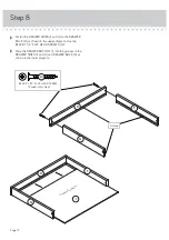
Step 4

Page 8

 å

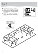
Push thirteen HIDDEN CAMS (1) into the ENDS (A),
UPRIGHTS (B and C), BACK (J) and FRONTS (K and L).

 å

Fasten the ENDS (A), UPRIGHTS (B and C), BACK (J)
and FRONTS (K and L) to the TOP (D). Tighten thirteen 
HIDDEN CAMS.  

 å

NOTE: Be sure the WOOD DOWELS in the ENDS,
UPRIGHTS, BACK and FRONTS insert into the holes in 
the TOP.

D

L

K

B

C

J

A

A

1

2

The arrow in the HIDDEN 
CAM must point toward the 
hole in the edge of the board.

Arrow

1

(13 used)

Summary of Contents for 5412885

Page 1: ...Something to write home about www teknikoffice co uk Writing Table Cinnamon Cherry Model 5412885 Teknik ...

Page 2: ...embly Tools Required Part Identification Hardware Identification Assembly Steps Français Español Safety Warranty No 2 Phillips Screwdriver Tip Shown Actual Size 3 4 5 15 16 18 19 21 22 23 Skip the power trip This time Page 2 ...

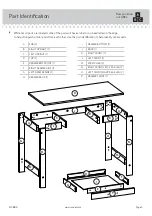
Page 3: ...o help identify similar parts Now you know our ABCs A END 2 B RIGHT UPRIGHT 1 C LEFT UPRIGHT 1 D TOP 1 E DRAWER BOX FRONT 1 F RIGHT DRAWER SIDE 1 G LEFT DRAWER SIDE 1 H DRAWER BACK 1 I DRAWER BOTTOM 1 J BACK 1 K RIGHT FRONT 1 L LEFT FRONT 1 M STRETCHER 2 N RIGHT FRONT LEFT REAR LEG 2 O LEFT FRONT RIGHT REAR LEG 2 P DRAWER FRONT 1 A B C D E K H I A F G J L M M N N O O P Page 3 www sauder com 412885...

Page 4: ...OD DOWEL 20 3 BLACK 2 FLAT HEAD SCREW 16 11 BLACK 1 1 2 FLAT HEAD SCREW 4 12 BLACK 1 1 8 PAN HEAD SCREW 12 13 BLACK 1 PAN HEAD SCREW 3 14 BLACK 3 4 MACHINE SCREW 2 15 BLACK 1 2 FLAT HEAD SCREW 14 16 SCREW COVER CARD 1 5 CAM COVER CARD 1 4 PULL 1 6 LEFT CABINET RAIL 1 18 RIGHT CABINET RAIL 1 17 LEFT DRAWER SLIDE 1 20 RIGHT DRAWER SLIDE 1 19 ...

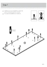
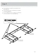
Page 5: ...Step 1 å Assemble your unit on a carpeted floor or on the empty carton to avoid scratching your unit or the floor å Turn thirteen CAM SCREWS 2 into the TOP D 2 13 used D Page 5 ...

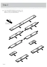
Page 6: ...Step 2 å Insert twenty WOOD DOWELS 3 into the holes in the edges of the ENDS A UPRIGHTS B and C BACK J FRONTS K and L and STRETCHERS M 3 20 used Page 6 J A A L M M K C B ...

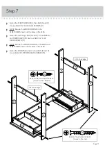
Page 7: ...SCREWS 11 å Fasten the FRONTS K and L to the ENDS A Use two BLACK 2 FLAT HEAD SCREWS 11 å Fasten the UPRIGHTS B and C to the BACK J and FRONTS K and L Use four BLACK 2 FLAT HEAD SCREWS 11 J A A L K B C Finished edge Finished edge BLACK 2 FLAT HEAD SCREW 8 used in this step 11 ...

Page 8: ... the ENDS A UPRIGHTS B and C BACK J and FRONTS K and L to the TOP D Tighten thirteen HIDDEN CAMS å NOTE Be sure the WOOD DOWELS in the ENDS UPRIGHTS BACK and FRONTS insert into the holes in the TOP D L K B C J A A 1 2 The arrow in the HIDDEN CAM must point toward the hole in the edge of the board Arrow 1 13 used ...

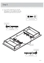
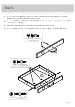
Page 9: ...GHT B and the LEFT CABINET RAIL 18 to the LEFT UPRIGHT C Use eight BLACK 1 2 FLAT HEAD SCREWS 16 through the exact holes shown below BLACK 1 2 FLAT HEAD SCREW 8 used in this step 16 Roller end 17 18 B C 17 18 Use these holes Use this hole Use these holes Use this hole ...

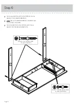
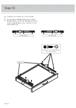
Page 10: ...HEAD SCREWS 11 å NOTE Be sure the WOOD DOWELS in the ENDS insert into the holes in the LEGS å Fasten the BACK J to the LEGS N and O Use six BLACK 1 1 8 PAN HEAD SCREWS 13 A A O N BLACK 2 FLAT HEAD SCREW 2 used for the LEGS 11 J BLACK 1 1 8 PAN HEAD SCREW 6 used for the BACK 13 ...

Page 11: ...GS N and O to the ENDS A and STRETCHERS M Use four BLACK 2 FLAT HEAD SCREWS 11 å NOTE Be sure the WOOD DOWELS in the ENDS and STRETCHERS insert into the holes in the LEGS å Fasten the FRONTS K and L to the LEGS N and O Use six BLACK 1 1 8 PAN HEAD SCREWS 13 A M A M O N N O Unfinished edge BLACK 2 FLAT HEAD SCREW 6 used in this step 11 Unfinished edge L K BLACK 1 1 8 PAN HEAD SCREW 6 used for the FRO...

Page 12: ...n the upper diagram Use two BLACK 1 1 2 FLAT HEAD SCREWS 12 å Slide the DRAWER BOTTOM I into the grooves in the DRAWER SIDES F and G and DRAWER BACK H as shown in the lower diagram H F G H F G I F i n i s h e d s u r f a c e Groove BLACK 1 1 2 FLAT HEAD SCREW 2 used in this step 12 ...

Page 13: ...IDES F and G as shown in the lower diagram Use two BLACK 1 1 2 FLAT HEAD SCREWS 12 å NOTE Be sure the DRAWER BOTTOM I inserts into the DRAWER BOX FRONT groove å Fasten the DRAWER FRONT P to the DRAWER BOX FRONT E Use three BLACK 1 PAN HEAD SCREWS 14 E F G P P 6 I BLACK 1 1 2 FLAT HEAD SCREW 2 used in this step 12 BLACK 3 4 MACHINE SCREW 2 used for the PULL 15 BLACK 1 PAN HEAD SCREW 3 used for the ...

Page 14: ...used in this step 16 å Carefully turn your drawer over onto its top edges å Fasten the RIGHT DRAWER SLIDE 19 to the RIGHT DRAWER SIDE F and the LEFT DRAWER SLIDE 20 to the LEFT DRAWER SIDE G Use six BLACK 1 2 FLAT HEAD SCREWS 16 Use these holes Use these holes 19 20 ...

Page 15: ...EN CAM å Peel the COVERS from the SCREW COVER CARD 5 and stick one onto each visible SCREW head å NOTE Please read this back page of the instruction booklet for important safety information å This completes assembly Clean with your favorite furniture polish or a damp cloth Wipe dry 5 40 lbs 40 lbs 5 lbs 5 lbs Place the roller on the SLIDE behind the roller on the RAIL To make drawer adjustments lo...

Page 16: ...rloaded drawers or shelves can break Never exceed the weight limits shown in the instructions Work from bottom to top when loading shelves and drawers Place the heavier items on the lower shelves or in lower drawers Placing TVs on furniture items that are not designed to support a television is hazardous Risk of injury or death TVs can be very heavy Plus the weight and location of the picture tube...

Reviews: