background image

ADDITIONAL SAFETY RULES FOR WOODLATHES 

!


Warning!

  Failure to follow these rules may result in serious personal injury. 

1. 

DO NOT MODIFY OR USE LATHE FOR USES 
OTHER THAN FOR WHICH IT WAS 
DESIGNED. 

2.

 SEEK 

INSTRUCTION. 

 If you are not


thoroughly 

familiar with the operation of woodlathes, obtain 
advice from your supervisor, instructor, or other 
qualified person. Instruction from a qualified 
person is strongly recommended.  

3.

  DO NOT OPERATE LATHE 

until it is completely 

assembled and installed.   

4.

  FOLLOW ELECTRICAL CODES.  

Make sure


wiring codes and recommended electrical 
connections are followed and that the machine is 
properly grounded.  

5.

  KEEP WORK AREA CLEAN. 

 Do not turn


the 

lathe On


before clearing the lathe of all objects 

(tools, scraps of wood, etc.).  Keep the nearby 
area and floor clear of debris. 

6. 

CHECK SET-UP

 with power Off.  Examine the


set-up carefully and rotate the


work piece by 

hand to check clearance before turning on 
power. 

7.

  DO NOT MAKE ADJUSTMENTS 

when the lathe 

or work piece is turning.  Make all adjustments 
with power Off. 

8.

  TIGHTEN ALL CLAMP HANDLES

 on the 

headstock, tailstock, and toolrest before 
operating lathe.  

9.

  EXAMINE WORK PIECE 

and glue joints before 

turning to make sure it has no defects that would 
cause it to break when turning.   

10.

  USE LOWEST SPEED

 when turning a new or 

unbalanced work piece. 

11.

  TURN AT RECOMMENDED SPEED.  

Always


operate the lathe at the recommended speeds. 
Consult this manual for suggested speeds. 

12.

 ADJUST TOOLREST 

close to the work piece.  

Before turning, revolve the stock by hand to 
make sure it clears the rest.  At intervals, stop 
the lathe and readjust the toolrest. 

13. 

KEEP TOOL ON TOOLREST.

  The lathe tool or 

chisel should be on the toolrest before the lathe 
is turned On.  Tools should remain on the 
toolrest whenever the tool is engaged in contact 
with the work piece. 

14.

 REMOVE TOOLREST 

when sanding or 

polishing so fingers do not get pinched. 


15.

  USE CORRECT LATHE TOOLS.  

Do not


use 

spindle turning chisels for faceplace mounted 
work, and vice versa.  Spindle turning tools used 
for faceplate turning may grab the work piece 
and pull the chisel from your control. 

16.

  WHEN ROUGHING STOCK 

do not


jam the 

lathe tool or chisel into work piece or take too big 
a cut. 

17.

  DO NOT POUND WORK PIECE

 into headstock 

drive (spur) center when turning between 
centers.  Pound the drive center into the work 
piece with a soft mallet before installing it 
between centers in the lathe.


18.

  DO NOT USE TAILSTOCK 

to drive work piece 

into the drive (spur) center when turning 
between centers.  Secure work between centers 
with light pressure from the tailstock quill action.   

19. 

FASTEN STOCK SECURELY BETWEEN 
CENTERS.  

Make sure the tailstock is locked 

before turning on the power. 

20.

  NEVER LOOSEN TAILSTOCK

 spindle or 

tailstock while work piece is turning.  

21.

  COORECTLY USE FACEPLATE. 

When


faceplate turning, make sure


work piece is 

securely fastened to the faceplate and that 
appropriate size faceplate is used to support the 
work piece. Any screw fasteners must not 
interfere with the turning tool at the finished 
dimension of the work piece. Rough-cut the


work 

piece as close as possible to finished shape 
before installing on faceplate. 

22.

  DO NOT OPERATE LATHE IF DAMAGED OR 

FAULTY.  

If


any part of your lathe is missing, 

damaged or broken, in any way, or any electrical 
component fails, shut off the lathe and 
disconnect the lathe from the power supply. 
Replace missing, damaged, or failed parts 
before resuming operation.   

23.

  ADDITIONAL SAFETY INFORMATION 

regarding the safe and proper operation of this 
product is available from the National Safety 
Council, 444 N. Michigan Avenue, Chicago, 
IL 60611 in the Accident Prevention Manual of 
Industrial Operations and also in the Safety Data 
Sheets provided by the NSC. Also refer to the 
American National Standards Institute ANSI 01.1 
Safety Requirements for Woodworking Machines 
and the U.S Department of Labor OSHA 
1910.213 Regulation.   


Guidelines to symbols used in this manual:  

!

 Warning Symbol. Pay close attention! 

L


Note/Information Symbol. Please read - important information for you.  

92-0106-017


Summary of Contents for NOVA 3000

Page 1: ...NOVA 3000 TM WOODLATHE Publication No 92 0106 017 Last updated 14 October 2003 I N S T R U C T I O N M A N U A L...

Page 2: ...grees It can be solidly locked in any position plus it has the added security of a detent pin lock at 0 22 5 45 90 plus 315 for left hand use The swivel head turns locks easily and has a very accurate...

Page 3: ...latest manuals downloadable from our website free newsletters projects etc We are only a phone call or email away with technical advice or assistance on the operation of your lathe or your woodturnin...

Page 4: ...nd Equipment Ltd Phone 1 604 522 5599 Free Phone 1 800 567 8979 Fax 1 604 522 0638 Email kmstools kmstools com Website www kmstools com United Kingdom Robert Sorby Phone 44 114 225 0700 Fax 44 114 225...

Page 5: ...indle Index 18 Headstock 18 Toolrest 19 Tailstock 20 Learning Turning 20 Maintaining the Nova 3000 21 General Maintenance 21 Cleaning the Toolslide 21 Cleaning the Tailstock 22 Aligning the Tailstock...

Page 6: ...re plugging in power cord 13 NEVER LEAVE MACHINE RUNNING UNATTENDED Do not leave tool unless it is turned off and has come to a complete stop 14 KEEP GUARDS IN PLACE and in working order 15 USE RIGHT...

Page 7: ...e spindle turning chisels for faceplace mounted work and vice versa Spindle turning tools used for faceplate turning may grab the work piece and pull the chisel from your control 16 WHEN ROUGHING STOC...

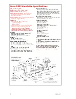
Page 8: ...step motor pulley 178 300 570 850 1200 1800 2400 3000 1 215 360 690 1030 1450 2180 2900 3630 2 Standard Equipment 300 mm 12 in Toolrest Poly Vee Drive Belt Motor Pulley Motor Mounting Kit 150 mm 6 in...

Page 9: ...p and the amount of work done The use of dust collectors and filters will minimize risks to your health Lathe Stand Recommendations A sturdy and rigid stand is required so that the Nova 3000 Woodlathe...

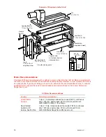
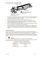
Page 10: ...athe in accordance with the recommendations outlined below However in most markets the motor is an optional extra If you are providing your own motor adhere to the recommendations below A variable spe...

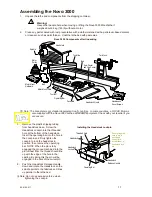
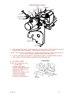
Page 11: ...ent Check with your reseller if you are unsure 3 Remove the plastic shipping tubing from headstock base Screw the Headstock Lockpin into the threaded hole at the bottom of the headstock Insert the ope...

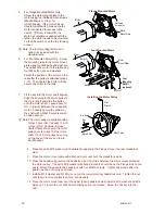
Page 12: ...ut 13 mm 1 2 inch between the pulley and motor Loosely secure the pulley to the shaft with a M8x10 set screw with an Allen wrench L Note The motor pulley is available with a 5 8 inch bore US Canada or...

Page 13: ...h the belt overhanging the outside of the pulley by one rib It is only on the bottom smallest step that all six ribs are used 13 Push the Teebar away from the lathe to increase the belt tension Tighte...

Page 14: ...prevent impact damage 3 Line up the dowel pin holes of the add on extension to the dowels and gently tap the end of the add on bed with a rubber or wooden mallet or using a metal hammer but with wood...

Page 15: ...h the outrigger end of headstock can be optionally used making a total of 8 bolt positions ensure that the bolt is a metric M12 x 1 75 mm pitch and that the length is correct to ensure that the bolt d...

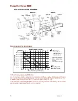
Page 16: ...nce work at slowest speed roughing stock general turning Key L Note Turning Speeds and DC Motors Use the electronic variable speed control in combination with the step pulley Variable speed DC motors...

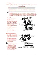
Page 17: ...n the teebar to hold the motor while the belt position is changed 4 Position the belt on the selected set of pulleys 5 Push the Teebar away from the lathe to tension the belt and tighten the teebar 6...

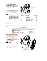
Page 18: ...3 6 9 12 15 18 21 every 3rd 45 12 0 2 4 6 8 22 every 2nd 30 24 every hole 15 Headstock The headstock houses the motor pulley headstock pulley bearings and the spindle The headstock spindle accepts cen...

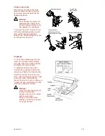
Page 19: ...for spur center Set spur center with mallet Toolrest To move the toolslide along the bed loosen the Toolslide Clamp Handle move the slide to the desired position and tighten the clamp handle To adjus...

Page 20: ...e work piece and insert the spur center into the headstock spindle as previously described under Using a Spur Center Warning Do not use the tailstock quill action to drive the work piece into the spur...

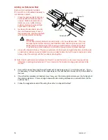
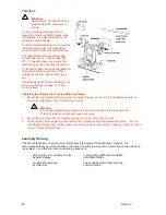
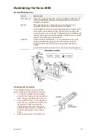
Page 21: ...oolslide front camshaft bore 6 Months Grease tailstock quill threads Turn the handwheel so the quill threads are exposed apply grease to the threads crank the handwheel back and forth to work in the g...

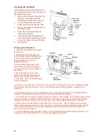
Page 22: ...from the headstock and extend and lock the quill The points of the centers should align when the quill is halfway extended fully extended and fully retracted If the centers are aligned at all three l...

Page 23: ...tor mount plate Check that the nyloc nuts on the headstock studs are tight and that the Teebar is tight Motor vibrates Many single phase motors due to their design produce minor noise or vibrations th...

Page 24: ...against the handwheel handle tap the handle in a clockwise direction as viewed from the tailstock end Build up of dust and wood resin on the quill or inside of the handwheel thread Remove clean and l...

Page 25: ...Nova 3000 Woodlathe Parts List See the parts list on page 26 92 0106 017 25...

Page 26: ...5 71Y 4 KC0608 3 8 x 1 UNC Allen Head Flathead Screws 71Q 4 CM5010192 M6 x 20 Allen Head Flathead Screws Item Qty Part No Description 1 1 24000 Main Lathe Bed 2 3 NN12 Nut Hex Nyloc M12 ZP 3 1 24023...

Page 27: ...e tightened one handed with an articulated key It includes a screw chuck A wide variety of optional jaws are available to hold almost any work piece SuperNova Chuck Small Toolrest A small 100 mm 4 in...

Page 28: ...sted in vacuum chucking this is a simple system Outrigger Unit Extend the bowl turning capacity of the Nova 3000 Woodlathe to up to 740 mm 29 in in diameter This unit is made from cast iron is easy to...

Page 29: ...Parts 16 Nova 3000 Specifications 8 Oil 21 Operating 17 21 Operating Bar 16 17 19 Ornamental Turner 28 Outrigger Unit 28 Parts List 25 26 Parts of the Nova 3000 11 16 25 26 Power 15 Problems 23 Quill...

Page 30: ...ster your warranty with Teknatool online Visit our website on www teknatool com to register your warranty faster today Or you can fill out the card below cut fold seal and post Teknatool Warranty Card...

Page 31: ...edges with sellotape glue tape etc 5 Affix appropriate Postage Stamps for postage to New Zealand and post 6 Optional List your return address details in the event of mishandled post Affix Postage Fold...

Page 32: ...Nova 3000 Woodlathe Manual Publication Code 92 0106 017 Teknatool International 2003 32 92 0106 017...

Reviews: