background image

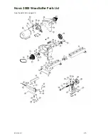
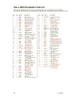
Nova 3000 Woodlathe Parts List 

Most items are applicable to all countries; items listed with an "Y

"

 are applicable to United States  

and Canada; items listed with "Q

"

 are applicable to New Zealand, Australia, UK, Europe, and South Africa. 

Item 

Qty 

Part No. 

Description 

37 

BHC08020 

Capscrew Button Head  

M8 x 20 

38 

FW8 

Washer Flat M8 x 16 ZP 

39 

FW12 

Washer Flat M12 ZP  

1.6 mm Thick 

40 

24008 

Lockplate Tailstock  

M12 ZP 1.6 mm Thick 

42 

2MTLC 

Live Center #2MT 

44 

24009 

Toolslide Casting  

45 

24048 

Cam Nut Toolslide  

46 

BNMZ12090 

M12 x 90 Eng Bolt  

47 

K1225 

M12 x 25 Allen Head  

Flathead Screw  

48 

27002 

Plate Toolslide Lock 

49 

24020 

Camshaft Toolslide 

50 

24026 

Teelock Body  

51 

HP-16 

Plughole M16 Black 

52 

24066 

Guard Headstock 

53Y 

24054 

Flange,  

Motor Mount NEMA 56C  

53Q 

24027 

Flange, Motor Mount Metric  

54 

24050 

Stud M12 x 60 Motor Mount 

55 

24051 

Stud M12 x 75 Motor Mount 

56 

24046 

Cam Casting for Motor Mount 

57 

24049 

Teebar - Motor Mount  

58 

24015 

Speed Indicator Label 

62 


Motor 

63Y 

MPWL 

Motor Pulley 8 step  

5/8 in. Shaft 

63Q 

MPWL19 

Motor Pulley 8 step  

M19 Shaft 

65 

584J6 

Belt Poly Vee 

66 

24055 

M5 x 10 Knob (guard cover) 

67 

MP05010 

Screw Pan Head Pozi  

M5 x 10 ZP 

69 

TR300/1 

Toolrest 300 mm with  

1 in. DIA post 

70Y 

FP150Y 

Faceplate 150 mm  

with 1-1/4 x 8 TPI 

70Q 

FP150Q 

Faceplate 150 mm  

with M30 x 3.5 

71Y 

KC0608 

3/8 x 1 UNC Allen Head 

Flathead Screws  

71Q 

CM5010192 

M6 x 20 Allen Head  

Flathead Screws  

Item 

Qty 

Part No. 

Description 

24000 

Main Lathe Bed  

NN12 

Nut Hex Nyloc M12 ZP 

24023 

Detent Pin D12 G/F #19 

24060 

Compression Spring 

24088 

Detent Pin Handle 

24001 

Bed Extension Unit  

24041 

Dowel Pin M12 x 36  

24011 

Capscrew M12 x 30  

24002 

Headstock  

10 (Y) 

24045 

Spindle Headstock  

1-1/4 x 8 TPI 

10 
(Q) 

24024 

Spindle Headstock  

M30 x 3.5 

10 (4) 

24103 

Spindle Headstock  

M33 x 3.5 

11 

6306LLB 

(Rear) NTN 6306 Bearing  

11Y 

6207LLB 

(Front) SKF 6207-2RSI 

Bearing 

11Q 

6306LLB 

(Front) NTN 6306 Bearing 

12 

EC30 

Circlip External 30mm  

(1.5 mm wide) 

13 

24080 

Wire Form Circlip 

14 

24025 

Pulley Headstock  

15 

24061 

3/16 in. SQ Key in  

M/S x 30 mm 

16 

2MTSPUR 

Spur Center #2MT 

17 

24062 

Spindle Index Knob 

18 

TP131658 

Bissel / Tension Pin  

3/16 in. x 5/8 

19 

24063 

Spindle Index Pin  

20 

DNNO8 

M8 Brass Dome Nut  

21 

G0810 

Set Screw M8 x 10  

Knurled Point 

22 

865913 

Ball Knob 3/4 in. DIA  

with M6 thread 

23 

25001 

TeeLock Arm M10 DIA x 85 

with M6 threads 

24 

55048 

Headstock Lockpin  

25 

24031 

Swivel Pin Headstock  

26 

24039 

Tailstock Adjustable Type  

27 

24064 

Quill Tailstock 1 in. DIA  

with M10 LH thread 

28 

24043 

Handwheel, Tailstock  

29 

24087 

Operating Bar 

30 

27001 

Key Quill Lock 

31 

24019 

Quill Lock Knob 

32 

24040 

Keeper Plate -  

Hardened Steel 

33 

G06010 

Set Screw M6 x 10  

Knurled Point 

34 

27000 

Lock Stud Tailstock  

35 

24016 

Lock Arms  

36 

24047 

Plate, Adjustable Alignment  


26 

92-9907-016


Summary of Contents for NOVA 3000

Page 1: ...NOVA 3000 TM WOODLATHE Publication No 92 0106 017 Last updated 14 October 2003 I N S T R U C T I O N M A N U A L...

Page 2: ...grees It can be solidly locked in any position plus it has the added security of a detent pin lock at 0 22 5 45 90 plus 315 for left hand use The swivel head turns locks easily and has a very accurate...

Page 3: ...latest manuals downloadable from our website free newsletters projects etc We are only a phone call or email away with technical advice or assistance on the operation of your lathe or your woodturnin...

Page 4: ...nd Equipment Ltd Phone 1 604 522 5599 Free Phone 1 800 567 8979 Fax 1 604 522 0638 Email kmstools kmstools com Website www kmstools com United Kingdom Robert Sorby Phone 44 114 225 0700 Fax 44 114 225...

Page 5: ...indle Index 18 Headstock 18 Toolrest 19 Tailstock 20 Learning Turning 20 Maintaining the Nova 3000 21 General Maintenance 21 Cleaning the Toolslide 21 Cleaning the Tailstock 22 Aligning the Tailstock...

Page 6: ...re plugging in power cord 13 NEVER LEAVE MACHINE RUNNING UNATTENDED Do not leave tool unless it is turned off and has come to a complete stop 14 KEEP GUARDS IN PLACE and in working order 15 USE RIGHT...

Page 7: ...e spindle turning chisels for faceplace mounted work and vice versa Spindle turning tools used for faceplate turning may grab the work piece and pull the chisel from your control 16 WHEN ROUGHING STOC...

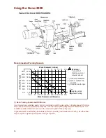
Page 8: ...step motor pulley 178 300 570 850 1200 1800 2400 3000 1 215 360 690 1030 1450 2180 2900 3630 2 Standard Equipment 300 mm 12 in Toolrest Poly Vee Drive Belt Motor Pulley Motor Mounting Kit 150 mm 6 in...

Page 9: ...p and the amount of work done The use of dust collectors and filters will minimize risks to your health Lathe Stand Recommendations A sturdy and rigid stand is required so that the Nova 3000 Woodlathe...

Page 10: ...athe in accordance with the recommendations outlined below However in most markets the motor is an optional extra If you are providing your own motor adhere to the recommendations below A variable spe...

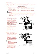
Page 11: ...ent Check with your reseller if you are unsure 3 Remove the plastic shipping tubing from headstock base Screw the Headstock Lockpin into the threaded hole at the bottom of the headstock Insert the ope...

Page 12: ...ut 13 mm 1 2 inch between the pulley and motor Loosely secure the pulley to the shaft with a M8x10 set screw with an Allen wrench L Note The motor pulley is available with a 5 8 inch bore US Canada or...

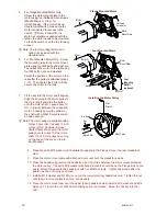
Page 13: ...h the belt overhanging the outside of the pulley by one rib It is only on the bottom smallest step that all six ribs are used 13 Push the Teebar away from the lathe to increase the belt tension Tighte...

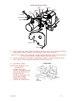
Page 14: ...prevent impact damage 3 Line up the dowel pin holes of the add on extension to the dowels and gently tap the end of the add on bed with a rubber or wooden mallet or using a metal hammer but with wood...

Page 15: ...h the outrigger end of headstock can be optionally used making a total of 8 bolt positions ensure that the bolt is a metric M12 x 1 75 mm pitch and that the length is correct to ensure that the bolt d...

Page 16: ...nce work at slowest speed roughing stock general turning Key L Note Turning Speeds and DC Motors Use the electronic variable speed control in combination with the step pulley Variable speed DC motors...

Page 17: ...n the teebar to hold the motor while the belt position is changed 4 Position the belt on the selected set of pulleys 5 Push the Teebar away from the lathe to tension the belt and tighten the teebar 6...

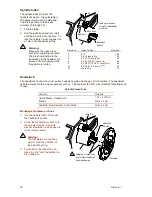
Page 18: ...3 6 9 12 15 18 21 every 3rd 45 12 0 2 4 6 8 22 every 2nd 30 24 every hole 15 Headstock The headstock houses the motor pulley headstock pulley bearings and the spindle The headstock spindle accepts cen...

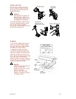
Page 19: ...for spur center Set spur center with mallet Toolrest To move the toolslide along the bed loosen the Toolslide Clamp Handle move the slide to the desired position and tighten the clamp handle To adjus...

Page 20: ...e work piece and insert the spur center into the headstock spindle as previously described under Using a Spur Center Warning Do not use the tailstock quill action to drive the work piece into the spur...

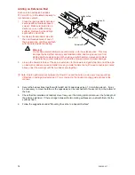
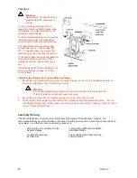
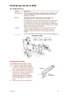
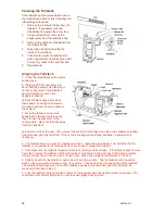
Page 21: ...oolslide front camshaft bore 6 Months Grease tailstock quill threads Turn the handwheel so the quill threads are exposed apply grease to the threads crank the handwheel back and forth to work in the g...

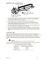
Page 22: ...from the headstock and extend and lock the quill The points of the centers should align when the quill is halfway extended fully extended and fully retracted If the centers are aligned at all three l...

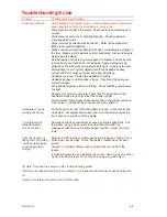
Page 23: ...tor mount plate Check that the nyloc nuts on the headstock studs are tight and that the Teebar is tight Motor vibrates Many single phase motors due to their design produce minor noise or vibrations th...

Page 24: ...against the handwheel handle tap the handle in a clockwise direction as viewed from the tailstock end Build up of dust and wood resin on the quill or inside of the handwheel thread Remove clean and l...

Page 25: ...Nova 3000 Woodlathe Parts List See the parts list on page 26 92 0106 017 25...

Page 26: ...5 71Y 4 KC0608 3 8 x 1 UNC Allen Head Flathead Screws 71Q 4 CM5010192 M6 x 20 Allen Head Flathead Screws Item Qty Part No Description 1 1 24000 Main Lathe Bed 2 3 NN12 Nut Hex Nyloc M12 ZP 3 1 24023...

Page 27: ...e tightened one handed with an articulated key It includes a screw chuck A wide variety of optional jaws are available to hold almost any work piece SuperNova Chuck Small Toolrest A small 100 mm 4 in...

Page 28: ...sted in vacuum chucking this is a simple system Outrigger Unit Extend the bowl turning capacity of the Nova 3000 Woodlathe to up to 740 mm 29 in in diameter This unit is made from cast iron is easy to...

Page 29: ...Parts 16 Nova 3000 Specifications 8 Oil 21 Operating 17 21 Operating Bar 16 17 19 Ornamental Turner 28 Outrigger Unit 28 Parts List 25 26 Parts of the Nova 3000 11 16 25 26 Power 15 Problems 23 Quill...

Page 30: ...ster your warranty with Teknatool online Visit our website on www teknatool com to register your warranty faster today Or you can fill out the card below cut fold seal and post Teknatool Warranty Card...

Page 31: ...edges with sellotape glue tape etc 5 Affix appropriate Postage Stamps for postage to New Zealand and post 6 Optional List your return address details in the event of mishandled post Affix Postage Fold...

Page 32: ...Nova 3000 Woodlathe Manual Publication Code 92 0106 017 Teknatool International 2003 32 92 0106 017...

Reviews: